Page 29
.
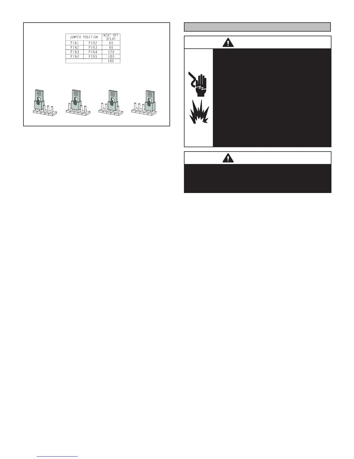
HEAT FAN‐OFF TIME IN SECONDS
To adjust fan-off timing, reposition jumper across pins to
achieve desired setting.
NO JUMPER
60
90
120
180
60
90
120
180
60
90
120
180
60
90
120
180
60 Second
off Time
90 Second
off Time
120 Second
off Time
180 Second
off Time
Figure 32
Constant Torque Motor
EL180UHE units are equipped with a constant torque ECM
motor. It has a DC motor coupled to an electronic control
module both contained in the same motor housing. The
motor is programmed to provide constant torque at each of
the ve selectable speeds. The motor has ve speed taps.
Each tap requires 24 volts to energize.
Input Voltage Requirements
The circuit is designed to be operated with AC voltage. A
voltage of 12 to 33VAC is required to energize the motor.
Expected current draw will be less than 20mA.
Blower Speeds
Follow the steps below to change the blower speeds.
1 - Turn off electrical power to furnace.
2 - Remove blower access panel.
3 - Disconnect existing speed tap at integrated control
speed terminal.
NOTE - Termination of any unused motor leads must be
insulated.
4 - Place unused blower speed tap on integrated
control “PARK” terminal or insulate.
5 - Refer to blower speed selection chart on unit wiring
diagram for desired heating or cooling speed.
See Product Specications manual for blower
performance data.
6 - Connect selected speed tap at integrated control
speed terminal.
7 - Resecure blower access panel.
8 - Turn on electrical power to furnace.
9 - Recheck temperature rise.
Electronic Ignition
The integrated control has an added feature of an internal
Watchguard control. The feature serves as an automatic
reset device for integrated control lockout caused by igni-
tion failure. This type of lockout is usually due to logas line
pressure. After one hour of continuous thermostat demand
for heat, the Watchguard will re-set and remake thermostat
demand to the furnace and automatically reset the integrat-
ed control to begin the ignition sequence.
Service
WARNING
ELECTRICAL SHOCK, FIRE,
OR EXPLOSION HAZARD.
Failure to follow safety warnings exactly
could result in dangerous operation, serious
injury, death or property damage.
Improper servicing could result in
dangerous operation, serious injury, death,
or property damage. Before servicing,
disconnect all electrical power to furnace.
When servicing controls, label all wires prior
to disconnecting.
Take care to reconnect wires correctly.
Verify proper operation after servicing.
WARNING
The blower door must be securely in place when the
blower and burners are operating. Gas fumes, which
could contain carbon monoxide, can be drawn into the
living space resulting in personal injury or death.
Annual Furnace Maintenance
At the beginning of each heating season, and to comply
with the Lennox Limited Warranty, your system should be
checked by a licensed professional technician (or equiva-
lent) as follows:
1 - Check wiring for loose connections, voltage at
indoor unit and amperage of indoor motor.
2 - Check the condition of the belt and shaft bearings
if applicable.
3 - Inspect all gas pipe and connections for leaks.
4 - Check the cleanliness of lters and change if
necessary (monthly).
5 - Check the condition and cleanliness of burners and
heat exchanger and clean if necessary.
6 - Check the cleanliness of blower assembly and
clean the housing, blower wheel and blower motor
if necessary . The blower motors are prelubricated
for extended bearing life. No further lubrication is
needed.
7 - IInspect the combustion air inducer and clean if
necessary.
8 - Evaluate the heat exchanger integrity by inspecting
the heat exchanger per the AHRI heat exchanger
inspection procedure. This procedure can be
viewed at www.ahrinet.org
 Loading...