Page 10
HEATING COMPONENTS
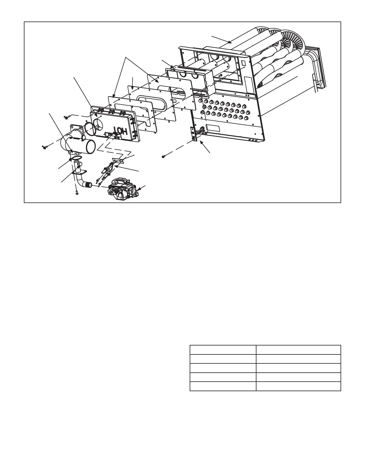
Gas Valve
Primary Limit
Ignitor
Sensor
Gas Orifice
Air Orifice
Rollout Switch
(location)
Air Gas Plenum
Gaskets
Burner
Heat Exchanger
Burner Box
FIGURE 5
B-Heating Components
Combustion air inducer (B6), primary limit control (S10),
ignitor, burners, ame rollout switch (S47), gas valve
(GV1), combustion air pressure switch (S18), and heat
exchangers are located in the heating compartment. The
heating compartment can be accessed by removing the
outer access panel.
1. Thermal Switch (Figure 5)
The auto-reset switch is located on the front of the air gas
intake. The switch will safely shut the unit down if exces-
sive temperatures are detected. When the switch senses
excessive temperature, the circuit breaks and the igni-
tion control immediately stops ignition and closes the gas
valve.
2. Primary Limit Control (S10)
The primary limit (S10) is located in the heating vestibule
panel. When excess heat is sensed in the heat exchanger,
the limit will open. If the limit is open, the furnace control
energizes the supply air blower and closes the gas valve.
The limit automatically resets when unit temperature re-
turns to normal. The switch must reset within three min-
utes or the SureLight control will go into Watch guard for
one hour. The switch is factory set and cannot be adjust-
ed. The switch may have a dierent set point for each unit
model number. See Lennox Repair Parts Handbook if limit
switch must be replaced.
3. Burner and Orice
Burners are factory set and require no adjustment. Always
operate the unit with air gas plenum in place. The burner
has one orice located between the gas valve and the air
intake assembly (Figure 5). To check or replace the orice
remove the black iron inlet pipe from the gas valve then
remove the four screws securing the gas valve to the in-
take air pipe. The orice is located in the orice housing.
The burner uses an orice (see Table 16) that is precisely
matched to the burner input. The burner can be removed
for service. If burner has been removed, it is critical to re-
place all gaskets.
TABLE 5
Orice Size
Unit Input Nat Orice Size (0 - 7500 ft)
040 0.0472
060 0.0595
080 0.0689
100 0.0810

 Loading...