Page 11
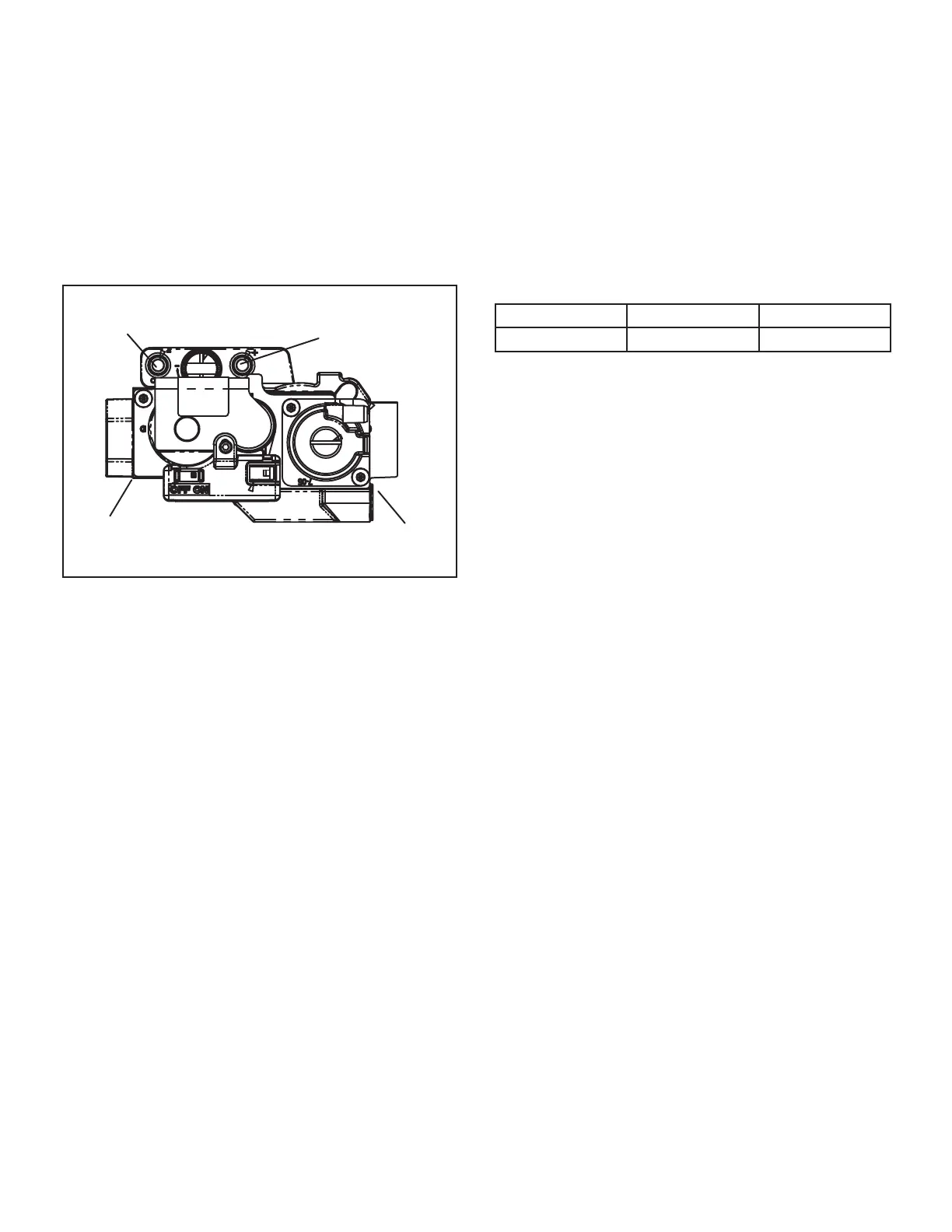
4. Gas Valve (Figure 6)
The EL195UHNE uses an internally redundant valve to
assure safety shut-o. If the gas valve must be replaced,
the same type valve must be used.
24VAC terminals and gas control switch are located on top
of the valve. All terminals on the gas valve are connected
to wires from the ignition control. 24V applied to the termi-
nals opens the valve.
Inlet and outlet pressure taps are located on the valve. A
manifold adjustment screw is also located on the valve. An
LP/Propane changeover kit is available.
NEGATIVE AIR
PRESSURE PORT
POSITIVE AIR
PRESSURE PORT
MANIFOLD
PRESSURE TAP
OUTLET
SUPPLY
PRESSURE
TAP
GAS VALVE
FIGURE 6
5. Flame Sensor (Figure 5)
A ame sensor is located on the top of the air gas plenum.
The sensor can be removed for service without remov-
ing the the burner. During operation, ame is sensed by
current passed through the ame and sensing electrode.
The SureLight control allows the gas valve to remain open
as long as ame signal is sensed. To check ame sense
signal use the push-button found on the integrated control
and go to Field Test Mode. The menu will display the ame
signal. See table 6 for ame signal.
TABLE 6
Flame Signal in Microamps
Normal Low Drop Out
2.6 or greater 2.5 or less 1.1
6. Ignitor (Figure 5)
EL195UHNE units use a nitride ignitor made from a pro-
prietary ceramic material. To check ignitor, measure its
resistance and voltage. A value of 39 to 70 ohms indi-
cates a good ignitor. Voltage to the ignitor should be 102
- 132VAC. See gure 7 for resistance and voltage checks.

 Loading...