Details of Intake and Exhaust Piping Terminations for
Direct Vent Installations
NOTE - In Direct Vent installations, combustion air is taken
from outdoors and ue gases are discharged to outdoors.
NOTE - Flue gas may be slightly acidic and may adverse-
ly aect some building materials. If any vent termination
is used and the ue gasses may impinge on the building
material, corrosion-resistant shield (minimum 24 inches
square) should be used to protect the wall surface. If the
optional tee is used, the protective shield is recommend-
ed. The shield should be constructed using wood, plastic,
sheet metal or other suitable material. All seams, joints,
cracks, etc. in the aected area should be sealed using an
appropriate sealant. See FIGURE 34.
-
1 -
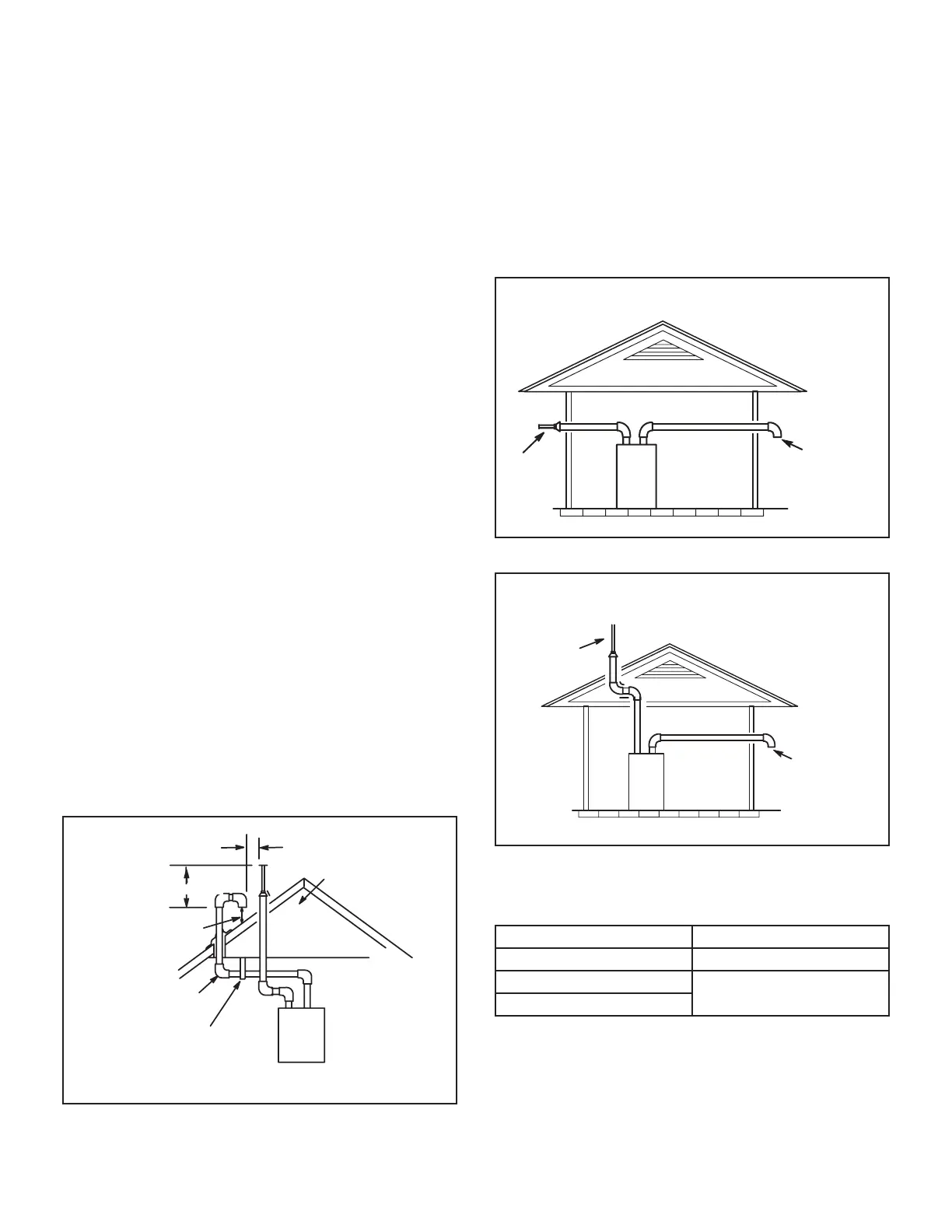
NOTE - When venting in dierent pressure zones,
the maximum separation requirement of intake and
exhaust pipe DOES NOT apply.
UNCONDITIONED
ATTIC SPACE
12” (305mm) ABOVE
AVERAGE SNOW
ACCUMULATION
3” (76mm) OR
2” (51mm) PVC
PROVIDE SUPPORT
FOR INTAKE AND
EXHAUST LINES
8” (203mm) MIN
Inches(mm)
DIRECT VENT ROOF TERMINATION KIT
(15F75 or 44J41)
FIGURE 35
NOTE - Care must be taken to avoid recirculation of
exhaust back into intake pipe.
6 -
Exhaust
Pipe
Furnace
Exiting Exhaust and Intake Vent
(different pressure zone)
Inlet Air
(Minimum 12 in.
305 MM) above
grade or snow
accumulation
FIGURE 36
Roof T
erminated
Exhaust Pipe
Furnace
Exiting Exhaust and Intake Vent
(different pressure zone)
Inlet Air
(Minimum 12 in.
305 MM) above
grade or snow
accumulation
FIGURE 37
TABLE 16
Exhaust Pipe Termination Size Reduction
 Loading...


