Do you have a question about the Lennox ELA Series and is the answer not in the manual?
Overview of Lennox ELA series air handler units and their applications.
Details on model numbers, tonnage, blower type, and circuits.
Evaporator coil specifications, including face area, split, and refrigerant.
Blower wheel size, filter type, and drive system specifications.
Accessories for blower, cabinet features, and control system integration.
Air filters, CO2 sensors, and related system accessories.
Performance data for ELA models by airflow and static pressure.
RPM ranges and motor horsepower for blower drive selection.
Data on electric heat sizes, voltage, kW, and circuit requirements.
Explanation of VFD, control board, and related components.
Details on freezestats, overflow relays, and inverter protection.
Overview of single or dual refrigerant circuits and distribution.
Steps for adjusting blower speed and belt tension for proper airflow.
Information on heating elements, contactors, and safety limits.
Role of sequencer relays, fuses, and transformer in electric heat.
How inverter-driven blowers operate for energy efficiency.
Procedures for setting minimum blower speeds and damper positions.
Mapping of LVC2 board terminals and proper operation verification.
Schematic illustrating electrical connections for blower and VFD.
Sequence for heating demand with ELS/ELP units.
Operation of electric heat stages based on thermostat signals.
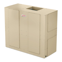
The Lennox ELA Series Air Handler Units are designed for upflow or horizontal air configurations and are intended for indoor applications. These units are compatible with Lennox ELS condensing units and Lennox ELP heat pump units, which are charged with HFC-410A refrigerant.
The primary function of the ELA Series Air Handler Units is to circulate conditioned air throughout a space. They are equipped with a Variable Frequency Drive (VFD) that modulates the blower motor's power frequency and voltage, allowing for staged blower speeds. This staging is responsive to cooling demand, heating demand, or ventilation demand, optimizing energy consumption by operating at lower speeds when demand is low and higher speeds when demand is high.
The units incorporate a refrigeration system, which, depending on the model, can be either a single refrigerant circuit (072 models) or a dual refrigerant circuit (090-240 models). Dual circuit units offer two-stage capacity control during cooling cycles, with each circuit having its own service valve connection and expansion valve.
For heating, the ELA units can be equipped with optional electric heat components. These components consist of helix-wound bare nichrome heating elements exposed directly to the air stream. Multiple-stage elements are sequenced on and off by time delays in response to thermostat demand, providing instantaneous heat transfer. Over-temperature protection is provided by primary and secondary high-temperature limits, and overcurrent protection is ensured by fuses.
Economizers can also be integrated, utilizing a relay (K43) to control their operation. When a call for cooling is initiated, the economizer is energized, allowing for fresh outdoor air intake.
The ELA units offer adjustable air volume, which can be set by modifying the adjustable pulley on the blower drive. This allows users to fine-tune the airflow to meet specific requirements. The VFD control board includes a ventilation speed switch that can be set to "LO" for energy savings during ventilation. Additionally, for units equipped with an economizer, minimum damper positions can be set for both high and low speeds using potentiometers on the VFD control board, ensuring adequate minimum ventilation air volumes in occupied mode.
The control system integrates various relays and switches for safe and efficient operation. For instance, the Inverter Protection Relay (K232) de-energizes the VFD if it trips, preventing damage. The Condensate Pan and Over Flow Relay (K220) and Switch (S149) are field-installed to prevent condensate overflow, de-energizing the unit if the drain is blocked and water levels rise. Freezestats (S49, S50) are strategically placed on the evaporator coils to prevent coil icing by temporarily disabling the respective compressor until the coil warms sufficiently.
Maintenance involves periodic checks and adjustments. The blower belt tension can be adjusted using a wrench on the tensioner body nut, aligning marks to ensure proper tension. The mounting bolt should then be tightened to secure the tensioner.
For troubleshooting the VFD control board (LVC2/A183), users can inspect for damaged components, check wire connections, and verify the 24VAC signal at the thermostat blower input. If the blower is rotating in the wrong direction, power wires from the VFD to the blower motor can be reversed. Regular verification of VFD operation includes measuring amp draw to the blower motor to ensure it does not exceed the Full Load Amperage (FLA) value listed on the motor nameplate.
The manual also emphasizes the importance of checking unit charge, airflow, and filters if freezestats are tripping frequently due to coil icing, to eliminate conditions that promote evaporator ice buildup. When replacing any wire in the appliance, it must be replaced with wire of like size, rating, insulation thickness, and termination. All power supplies must be disconnected before servicing to prevent electric shock hazards. The unit must also be grounded in accordance with national and local codes.
| Product Type | Air Handler |
|---|---|
| Series | ELA |
| Airflow | Up to 2000 CFM |
| Dimensions | Varies by model |
| Weight | Varies by model |
| Cooling Capacity | 18, 000-60, 000 BTU/h |
| Motor Type | ECM |
| Cabinet | Galvanized steel |
| Voltage | 208/230V |
| Filter Type | Standard 1" Filter |


 Loading...