Page 22
ELA Supply Air Inverter Startup
A-General
Units equipped with a supply air inverter are available
which provide two blower speeds. The blower will operate
at lower speeds when cooling demand is low and higher
speeds when cooling demand is high. This results in lower
energy consumption.
Inverter-driven blowers will operate at high speed during
ventilation (blower “G” only signal) but can be adjusted to
operate at low speed.
Low speed is approximately 2/3 of the full speed RPM.
B-Set Maximum Blower CFM
1 - Initiate a blower (G) only signal from the room
thermostat or control system.
2 - Adjust the blower pulley to deliver the full (high
speed) CFM in the typical manner. See Determining
Unit CFM in the Blower Operation and Adjustment
section.
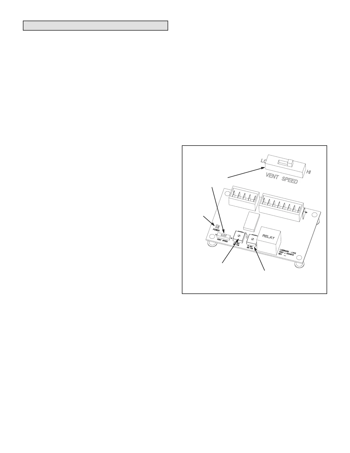
C-Set Blower Speed During Ventilation
To save energy during ventilation, the blower speed can
be set to low. This is accomplished by changing the venti-
lation speed switch on the VFD control board to “LO”. See
gure 17.
NOTE – On units equipped with an economizer, set damp-
er minimum position as shown in the next section. After
adjusting the low speed minimum position, the ventilation
speed switch will be in the “LO” position.
D-Set Damper Minimum Position (Units with Econo-
mizer)
To maintain required minimum ventilation air volumes
when the unit is in the occupied mode, two minimum
damper positions must be set. A high and a low speed
potentiometer are provided on the VFD control board to
adjust minimum damper position. See gure 17.
Set High Speed Minimum Position
1 - Initiate a blower (G) only AND occupied demand
from the room thermostat or control system.
2 - Set the ventilation speed switch on the VFD control
board to “HI”.
3 - Rotate the high speed potentiometer on the VFD
control board to set the high speed minimum
damper position.
4 - Measure the intake air CFM. If the CFM is lower
than the design specied CFM for ventilation air,
use the potentiometer to increase the damper
percent open. If the CFM is higher than specied,
decrease the damper percent open.
NOTE – Intake air CFM can also be determined using the
outdoor air temperature, return air temperature and mixed
air temperature. Refer to the economizer or outdoor air
damper installation instructions.
Set Low Speed Minimum Position
1 - Initiate a blower (G) only AND occupied demand
from the room thermostat or control system.
2 - Set the ventilation speed switch on the VFD control
board to “LO”.
3 - Rotate the low speed potentiometer on the VFD
control board to set the low speed minimum damper
position.
4 - Measure the intake air CFM. If the CFM is lower
than the design specied CFM for ventilation air,
use the potentiometer to increase the damper
percent open. If the CFM is higher than specied,
decrease the damper percent open.
NOTE – Intake air CFM can also be determined using the
outdoor air temperature, return air temperature and mixed
air temperature. Refer to the economizer or outdoor air
damper installation instructions.
LVC2 (A183) VFD CONTROL BOARD
VENTILATION
SPEED SWITCH
LOW SPEED
MINIMUM POSITION
POTENTIOMETER
HIGH SPEED
MINIMUM POSITION
POWER
LED
FIGURE 5
Troubleshoot LVC2 Board (A183)
Refer to wiring diagram sections B (unit), C (control) and D
(economizer) located on inside of unit panels.
1 - Inspect the LVC2 for damaged components. Replace
the LVC2 if damaged components are found.
2 - Check all wire connections to LVC2; secure if loose.
3 - Check for 24VAC signal at the thermostat blower
input (G to GND terminal). See gure 3.

 Loading...

