EasyManua.ls Logo

Lennox EL240XASD User Manual

Lennox EL240XASD
31 pages
To Next Page IconTo Next Page
Page #1 background imageLoading...
Page #1 background image
Page 1
WARNING
Improper installation, adjustment, alteration, service
or maintenance can cause property damage, personal
injury or loss of life. Installation and service must be
performed by a licensed professional HVAC installer or
equivalent, service agency, or the gas supplier.
IMPORTANT
The Clean Air Act of 1990 bans the intentional venting of
refrigerant (CFCs, HCFCs and HFCs) as of July 1, 1992.
Approved methods of recovery, recycling or reclaiming
must be followed. Fines and/or incarceration may be
levied for noncompliance.
WARNING
Electric shock hazard! - Disconnect all power
supplies before servicing.
Replace all parts and panels before
operating.
Failure to do so can result in death or
electrical shock.
WARNING
To prevent serious injury or death:
1. Lock-out/tag-out before performing maintenance.
2. If system power is required (e.g., smoke detector
maintenance), disable power to blower, remove fan
belt where applicable, and ensure all controllers
and thermostats are set to the “OFF” position before
performing maintenance.
3. Always keep hands, hair, clothing, jewelry, tools, etc.
away from moving parts.
Table of Contents
SPECIFICATIONS .......................................................... 2
BLOWER DATA ..............................................................4
I - UNIT COMPONENTS ..............................................19
II − REFRIGERATION SYSTEM ..................................20
III − BLOWER SPEED & BELT TENSION ....................20
IV − Electric Heat Components ....................................21
Supply Air Inverter Startup............................................22
Verify Proper Operation ................................................ 23
Sequence of Operation ................................................24
ELXA
6 – 20 TONS
Service Literature
UNIT INFORMATION
100069
April 20, 2023
ELXA SERIES AIR HANDLER UNITS
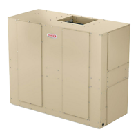
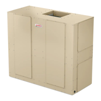
ELXA series blower−coil units are designed for upow or
horizontal air and indoor applications only. ELXA blower
units are available in six models; 072, 090, 120, 150, 180
and 240. The units match up with ELXC condensing units
and ELXP heat pump units charged with HFC−410A re-
frigerant.
Information and specications contained in this manual
are subject to change. Procedures outlined in this manual
are presented as a recommendation only and do not su-
persede or replace local or state codes.
CAUTION
As with any mechanical equipment, contact with sharp
sheet metal edges can result in personal injury. Take
care while handling this equipment and wear gloves and
protective clothing.
Question and Answer IconNeed help?

Do you have a question about the Lennox EL240XASD and is the answer not in the manual?

Lennox EL240XASD Specifications

General IconGeneral
ModelEL240XASD
AirflowUp to 2000 CFM
RefrigerantR-410A
TypeAir Handler
Cooling CapacityUp to 5 tons (60, 000 BTU)
Heating CapacityVaries with electric heat kit
Nominal Heating CapacityN/A (Electric Heat Kit Optional)
Motor TypePSC or ECM (Depending on Model)
Coil TypeAluminum
Voltage208/230V, 1 Phase

Summary

ELXA Series Air Handler Units

Unit Specifications

Details general unit data, connections, refrigerant, and coil specifications.

Options and Accessories

Lists available optional components such as electric heat, economizers, and sensors.

Blower Performance Data

Blower Drive Specifications

Details motor HP and RPM ranges for blower drive configurations across models.

Blower Motor Electrical Data

Provides electrical specs for blower motors, including ampacity and load amps.

Accessory Air Resistance

Lists air resistance values for accessories like filters, economizers, and coils.

Unit Components and Systems

Key Unit Components

Describes major components like VFD, freezestats, and control boards.

Refrigeration System Details

Explains refrigerant circuit configuration and capacity control for the units.

Blower Speed and Belt Adjustment

Guides for adjusting blower speed and belt tension for optimal airflow.

Electric Heat Operation

Electric Heat Components

Explains heating elements, contactors, fuses, and safety limits.

Electric Heat Sequence of Operation

Details activation of electric heat stages based on thermostat demand and safety.

Control and Inverter System

Supply Air Inverter Startup

Procedures for starting and configuring the supply air inverter for blower control.

LVC2 Board Troubleshooting

Steps to diagnose and resolve issues with the LVC2 VFD control board.

Verify Proper Operation

Checks for correct blower rotation, wiring, and motor performance.

Sequence of Operation and Wiring

Sequence of Operation

Describes the operational logic for cooling and heating sequences.

Unit Wiring Diagrams

Illustrates electrical connections for unit components, controls, and power.

Related product manuals