Page 21
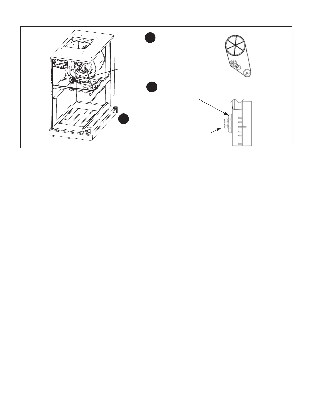
Adjusting Belt Tension
Place belt over all three pulleys.
Using a 15/16" wrench on the
tensioner body nut, apply force until
marks align as shown.
While holding the tensioner in this position,
tighten the mounting bolt to 23 ft−lbs using
a 9/16" wrench.
1
2
3
BELT TENSIONER
FIGURE 4
IV − Electric Heat Components
See electric heat tables (table of contents) for electric heat
matchups. EHA units consists of electric heating elements
exposed to the air stream. Multiple−stage elements are
sequenced on and off by time delays in response to ther-
mostat demand.
1 − Heating Elements HE1, HE2, HE3 and HE4
Heating elements are composed of helix wound bare ni-
chrome exposed directly to the air stream. Heating ele-
ments are energized directly by contactors. Once ener-
gized, heat transfer is instantaneous. Over temperature
protection is provided by primary and secondary high tem-
perature limits. Overcurrent protection is provided by fuses.
Each stage of electric heat consists of three elements con-
nected in a three-phase arrangement. Elements in 208/230V
units are connected in a “Delta” arrangement. Elements in
460 and 575V units are connected in a “Wye” arrangement.
Each stage is energized independently by a three-pole dou-
ble-break contactor and is protected by safety limits.
2 − Contactors K15 and K16
Contactors K15 and K16 are three−pole double break re-
lays with a 24 volt coil that energize their respective heating
elements on thermostat demand. K15 energizes rst stage
heat elements and K16 energizes second stage elements.
3 − Electric Heat Sequencer Relays K32
Relay K32 is a N.O. sequencer relay with a resistive ele-
ment for a coil and a bi-metal disk which actuates the con-
tacts. The relays are located on the electric heat vestibule
panel and are energized by a 24V heating demand (W1,
W2). When energized, the internal resistance heats the
bi-metal disk causing the contacts to close. When the re-
lay is de-energized, the disk cools and the contacts open.
The relay energizes different stages of heat.
4 − Relays K9 and K19
Relays K9 and K19 are used to electrically isolate the ELA 24
volts components from the T3EHA 24 volt components. The
coil on the relays are connected to rst stage and second
stage heat. On a rst stage heat demand K9 is energized.
K9−1 closes energizing rst stage heat contactor K15. On a
second stage heat call K19 is energized. When K19−1 clos-
es contactor K16 is energized which energizes relay K32.
5 − Fuse F3
Heating elements in all T3EHA units are protected by fuse
F3. The fuse is connected in series with each leg of elec-
tric heat.
6 − Fuse F4
F4 serves the same purpose as F3 but is in line with line
volt-age and protects the indoor blower.
7 − Transformer T2
T2 is line voltage to 24VAC which provides 24VAC to pow-
er to all T3EHA contactor coils, relays and timers.
8 − High Temperature Limit S15 (Primary)
S15 is the primary high temperature limit. It is located in
the electric heat unit immediately downstream from the
heating elements. S15 is a single-pole single-throw nor-
mally closed thermostat wired in series with the rst stage
contactor coil.
When S15 opens, indicating a problem in the system, con-
tactor K15 is de-energized. When K15 is de-energized, rst
stage and all subsequent stages of heat are de-energized.
Since the indoor blower is controlled by demand (K9 re-
mains energized), the indoor blower continues operating.
9 − High Temperature Limit S20 (Secondary)
Each heating element assembly is electrically connected
to two high temperature limits S20 (refer to wiring dia-
grams in back of this manual). Each limit is connected in
series with one leg of the three-phase element assembly.
The third leg of each assembly is not equipped with a lim-
it. Three-phase operating characteristics allow one of the
other two limits to protect the third leg.

 Loading...

