NOTE - Cold end header box drain plugs are factory
installed. Check the unused plug for tightness to
prevent leakage.
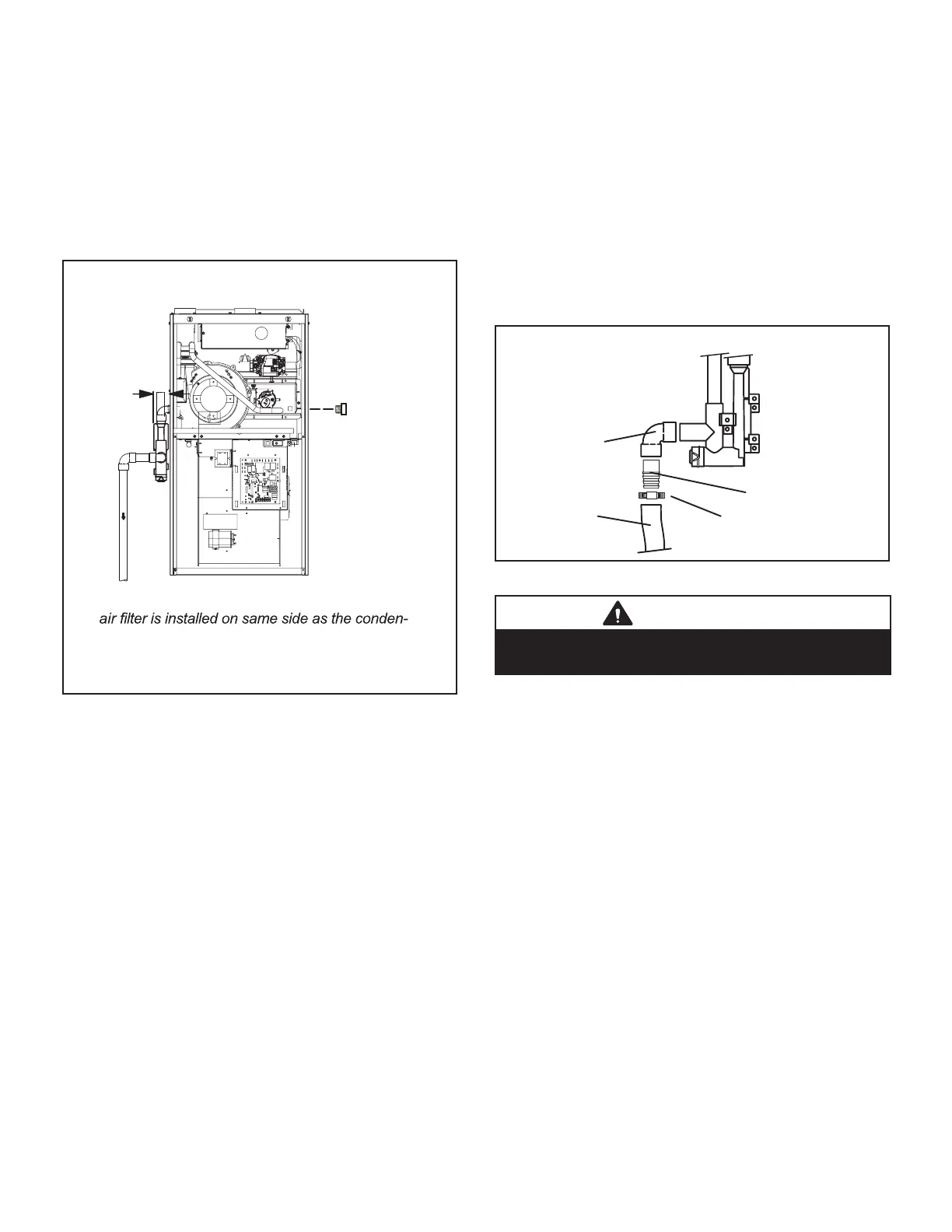
CONDENSATE TRAP AND PLUG LOCATIONS
(Unit shown in upflow position)
NOTE - In upflow applications where side return
sate trap, filter rack must be installed beyond
condensate trap or trap must be re-located to
Trap
(same on
right side)
Plug
(same on left side)
1-1/2 in.
FIGURE 46
Upow furnace (FIGURE 52) -
Horizontal furnace (FIGURE 53) -
NOTE - In horizontal applications it is recommended
to install a secondary drain pan underneath the unit
and trap assembly.
NOTE - Appropriately sized tubing and barbed tting
may be used for condensate drain. Attach to the
drain on the trap using a hose clamp. See FIGURE
47.
Field Provided Drain Components
Tubing
Hose Clamp
Barbed Fitting
Elbow
FIGURE 47
CAUTION
Do not use copper tubing or existing copper
condensate lines for drain line.
6 -
 Loading...


