Page 17
IV−Charging
WARNING
Refrigerant can be harmful if it is inhaled. Refrigerant
must be used and recovered responsibly.
Failure to follow this warning may result in personal
injury or death.
A−12CHP
For maximum performance of this heat pump system, the
operating temperatures and pressures should be checked
and superheat determined at Standard ARI test conditions
of 82_F outdoor − 80_F indoor dry bulb/67_F wet bulb. If su-
perheat measured deviates from values in table 6, refriger-
ant charge should be adjusted accordingly for maximum
performance.
Verify system performance using table 7 or table 8 as a gen-
eral guide. These tables should not be used for charging the
unit. Minor variations in these pressures may be expected
due to differences in installations. Significant differences
could mean that the system is not properly charged or that a
problem exists with some component in the system. Used
carefully, this table could serve as a useful service guide.
Table 7 should be used when unit is charged during the
heating mode. If outdoor ambient is below 45°F, run unit
through defrost cycle first, wait 15 minutes for system pres-
sures to stabilize, then take pressures. Data in table 7 is
based on 70°F dry bulb return air. Data in table 8 is based
on 80°F dry bulb / 87°F wet bulb return air. Allow unit opera-
tion to stabilize before taking pressure readings.
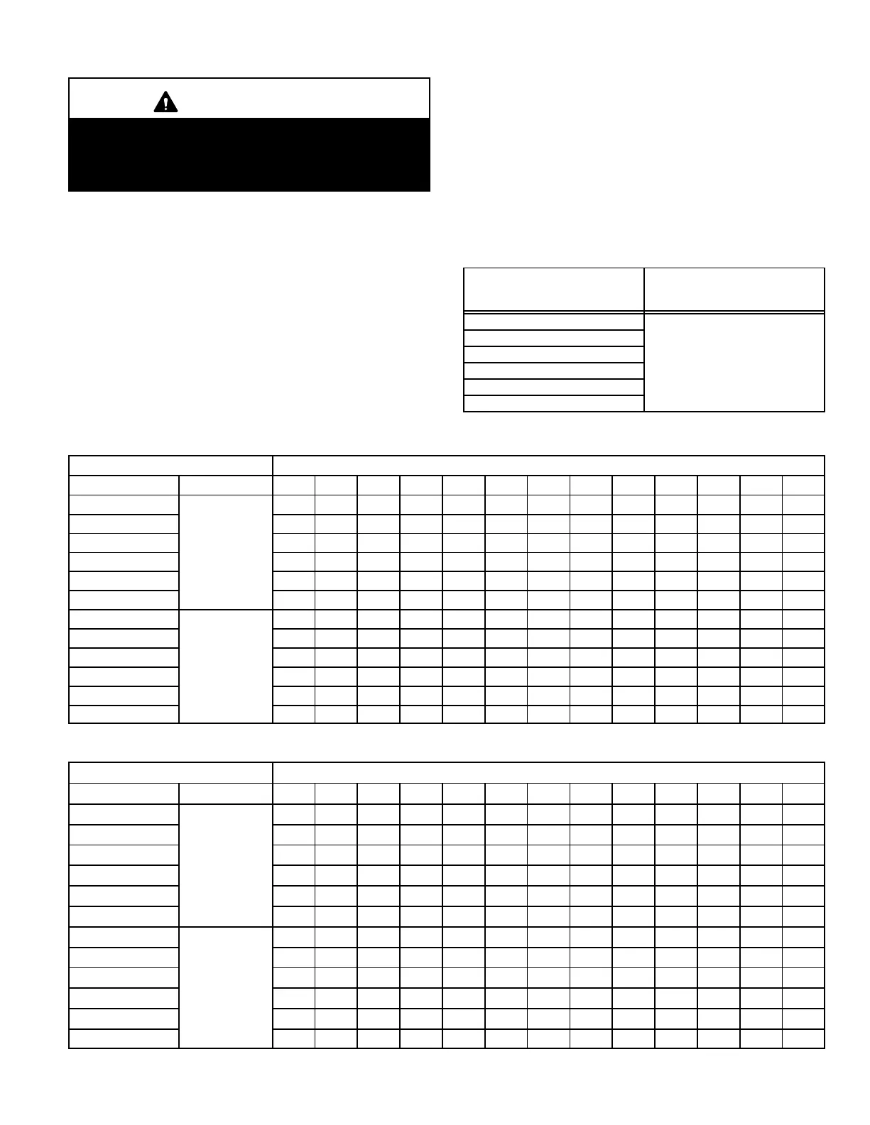
TABLE 6
12CHP SUCTION SUPERHEAT TABLE
UNIT MODEL NO.
SUCTION SUPERHEAT
82_F OD − 80_F IDDB
/ 67_F IDWB
12CHP−024
12CHP−030
12CHP−036
18 − 20_
12CHP−042
12CHP−048
12CHP−060
TABLE 7
NORMAL OPERATING PRESSURES −− HEATING MODE
70°F db RETURN AIR AIR TEMPERATURE ENTERING OUTDOOR COIL (°F)
MODEL PRESSURE 0° 5° 10° 15° 20° 25° 30° 35° 40° 45° 50° 55° 60°
12CHP−024 17 20 24 28 33 38 43 49 55 62 69 74 81
12CHP−030 14 17 21 25 29 34 39 45 51 56 63 70 78
12CHP−036
14 17 21 25 29 34 39 45 51 56 63 70 78
12CHP−042
16 19 23 27 31 36 41 45 51 55 62 68 76
12CHP−048 15 18 22 26 30 35 40 45 51 55 62 68 76
12CHP−060 14 17 21 25 29 34 39 44 50 54 61 67 75
12CHP−024 181 191 200 209 219 228 237 247 256 265 275 284 293
12CHP−030 168 173 179 184 189 195 200 205 211 216 221 227 232
12CHP−036
165 172 178 184 191 197 203 210 216 222 229 235 241
12CHP−042
167 174 181 187 194 201 207 214 221 227 234 241 247
12CHP−048 203 211 220 229 237 246 255 263 272 281 289 298 307
12CHP−060 163 170 177 183 190 197 203 210 217 223 230 237 243
TABLE 8
NORMAL OPERATING PRESSURES −− COOLING MODE
80°F db / 67°F wb RETURN AIR AIR TEMPERATURE ENTERING OUTDOOR COIL (°F)
MODEL PRESSURE 65° 70° 75° 80° 82° 85° 90° 95° 100° 105° 110° 115° 125°
12CHP−024 78 79 81 82 83 84 85 87 89 90 92 93 96
12CHP−030 78 79 81 82 83 84 85 87 89 90 92 93 96
12CHP−036
75 77 80 82 83 84 87 89 91 94 96 98 103
12CHP−042
80 81 82 84 84 85 86 87 88 89 90 92 94
12CHP−048 78 79 80 82 82 83 84 85 86 87 88 90 92
12CHP−060 78 79 80 82 82 83 84 85 86 87 88 90 92
12CHP−024 140 155 170 184 190 199 213 228 243 257 272 286 316
12CHP−030 145 159 173 187 193 202 216 230 244 258 273 287 315
12CHP−036
LIQUID
146 161 176 191 197 206 221 236 251 266 281 296 326
12CHP−042
155 170 185 200 206 215 230 245 260 275 290 305 335
12CHP−048 164 180 196 213 219 229 245 261 277 293 309 326 358
12CHP−060 166 182 198 214 220 229 245 261 277 293 308 324 356
 Loading...