© 2000 Lennox Industries Inc.
Litho U.S.A.
Page 1
Corp. 0003−L3
Service Literature
2 to 5 Ton (7.0 to 17.6 kW)
12GCS/12CHP
Revised 06−2004
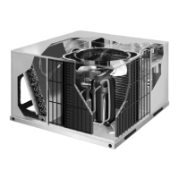
12GCS/12CHP ELITE SERIES UNITS
The 12GCS packaged heat/cool units, are available in sizes
ranging from 2 through 5 tons (7.0 through 17.6 kW). 12GCS
series units are designed for outdoor residential use only.
Units can be installed at ground level or roof top applications.
Gas heat sections are available with Lennox S−curve heat ex-
changers in 50,000, 75,000, 100,000 and 125,000 Btuh input
sizes.
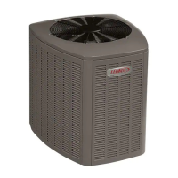
The 12CHP packaged heat pump units are available in
sizes ranging from 2 through 5 tons (7.0 through 17.6 kW).
12CHP units are designed for outdoor residential use only.
Units can be installed at ground level or rooftop applica-
tions. Optional field installed supplemental electric heat is
available in 5, 7, 10, 15 and 20 kW.
Both the 12GCS and 12CHP units utilize a scroll compres-
sor. It operates much like a standard compressor, but the
scroll compressor is unique in the way that it compresses
refrigerant. The compressor has overload protection and its
own cover for reducing operating sound levels.
Information contained in this manual is intended for use by
qualified service technicians only. All specifications are sub-
ject to change. Procedures outlined in this manual are pre-
sented as a recommendation only and do not supersede or
replace local or state codes.
WARNING
Improper installation, adjustment, alteration, service
or maintenance can cause property damage, person-
al injury or loss of life. Installation and service must
be performed by a qualified installer or service
agency.
ELECTROSTATIC DISCHARGE (ESD)
Precautions and Procedures
CAUTION
Electrostatic discharge can affect electronic
components. Take precautions during unit instal-
lation and service to protect the unit’s electronic
controls. Precautions will help to avoid control
exposure to electrostatic discharge by putting
the unit, the control and the technician at the
same electrostatic potential. Neutralize electro-
static charge by touching hand and all tools on an
unpainted unit surface before performing any
service procedure.
12GCS
12CHP
TABLE of CONTENTS
Introduction....................................................................1
Specifications/Blower Data 12GCS.............................2,4
High Altitude 12GCS.......................................................4
Specifications/Blower Data 12CHP.............................5,6
Parts Arrangement......................................................7,8
I Application ...................................................................9
II Unit Components ...................................................9,14
III Electric Heat .........................................................15,17
IV Charging ..............................................................18,19
V Maintenance ........................................................... 20
VII Wiring Diagram and Sequence of Operation .......... 21