Page 9
I−APPLICATION
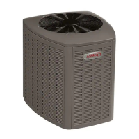
12GCS 2 through 5 ton (7.0 through 17.6kW) model units
are single packaged heat/cool units designed for outdoor
installation on a slab or rooftop.The units are available in
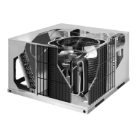
three cabinet sizes. 12CHP 2 through 5 ton (7.0 through
17.6kW) model units are available in three cabinet sizes and
are designed for outdoor installation on a slab or rooftop.
Electric heat can be factory or field installed if required.
12GCS/12CHP units are single−phase and residential only.
Refer to the Engineering Handbook for more specific ap-
plication data.
II−UNIT COMPONENTS
12GCS components are shown in figure 1. 12CHP compo-
nents are in figure 2. Component description will be broken
down into three categories: Control box, Gas and Cooling.
Some control box and cooling components will be shared by
both 12GCSmodel units and 12CHP model units. These com-
ponents will be identified as all models . Other components
will be identified as either GCS only" or CHP only"
A−Control Box Components
12GCS control box components are shown in figure 3. 12CHP
control box components are shown in figure 4.
1−Compressor Contactor K1 (all models)
K1 is a 24VAC to line voltage two pole double break contactor,
which energizes the compressor and condenser fan in re-
sponse to thermostat demand.
2−Control Transformer T1 (all models)
All 12GCS/12CHP series units use line voltage to 24VAC
transformer mounted in the control box. The transformer sup-
plies power to control circuits in the unit. Transformers use two
primary voltage taps as shown in figure 5.
FIGURE 5
240 VOLTS
208 VOLTS
PRIMARY
SECONDARY
208 / 240 VOLT TRANSFORMER
24 VOLTS
L1
L2
3−Dual Capacitor C12 (all models)
The compressor and condenser fan in the 12GCS/12CHP se-
ries units use permanent split capacitor motors. The capacitor
is located in the control box. A dual rated capacitor is used for
both the condenser fan motor and the compressor (see unit
wiring diagram per respective unit). The fan side and the com-
pressor side of the capacitor have different MFD ratings. See
side of capacitor for ratings.
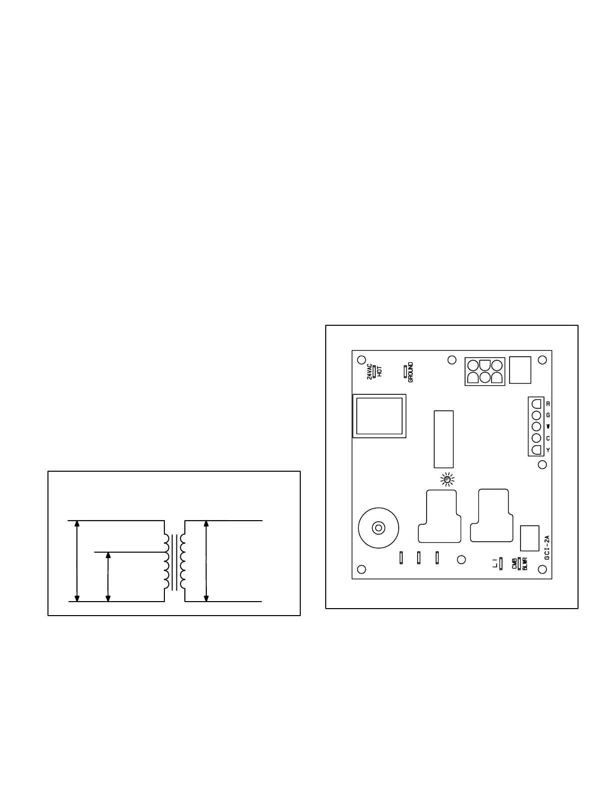
4−Ignition/Blower Control A3 (GCS only)
All 12GCS series units are equipped with an integrated ignition
/ blower board (A3) which controls ignition, safety circuits,
blower operation and fan off timing. See figure 6. Table 1
shows jack plug terminal designations.
Ignition control
All 12GCS units use direct spark ignition which is controlled by
an integrated ignition control board. On a call for heat the con-
trol monitors the combustion air prove switch. The control will
not begin the heating cycle if the prove switch is closed (by−
passed). Once the prove switch is determined to be open, the
combustion air inducer blower is energized. When the differen-
tial in the prove switch is great enough, the switch closes and a
30−second pre−purge begins. After the pre−purge period, the
gas valve opens and ignition (spark) is attempted for 10 sec-
onds. If the initial attempt for ignition fails, the sequence is re-
peated two more times. After a total of three failed attempts,
the board goes into Watchguard. During watchguard mode,
the board is de−energized for one hour. After one hour the con-
trol will repeat the ignition sequence. Watchguard may be
manually reset by breaking and remaking thermostat demand.
FIGURE 6
THERMOSTAT
CONNECTIONS
6 PIN PLUG 24VAC
LED DIAGNOSTIC
CONDITIONS
SPARK IGNITION
1
3
2
4
5
6
12GCS INTEGRATED CONTROL
BLOWER SPEED
TERMINALS
Safety Circuits
During the heating cycle the control monitors the safety circuits.
If the primary or secondary heating limits open, the control de−
energizes the gas valve and combustion air inducer blower
while the indoor blower remains energized. When the limit au-
tomatically resets the ignition sequence also resets.
If the rollout switch opens, the control de−energizes the gas
valve and the combustion air inducer blower. The unit will re-
main de−energized until the rollout switch is manually reset.
 Loading...