Page 14
D−Cooling Components
1−Compressor B1 (all models)
All 12GCS/12CHP units utilize a scroll compressor. Compres-
sors are energized by contactors found in unit control box.
Compressor specifications are found in the ELECTRICAL
DATA" section in this manual.
WARNING
Electrical shock hazard. Compressor must be
grounded. Do not operate without protective cover
over terminals. Disconnect power before removing
protective cover. Discharge capacitors before ser-
vicing unit. Failure to follow these precautions could
cause electrical shock resulting in injury or death.
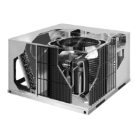
FIGURE 12
SCROLL COMPRESSOR
DISCHARGE
SUCTION
The scroll compressor design is simple, efficient and re-
quires few moving parts. A cutaway diagram of the scroll
compressor is shown in figure 12. The scrolls are located in
the top of the compressor can and the motor is located in
the bottom of the compressor can. The oil level is immedi-
ately below the motor.
The scroll is a simple compression concept centered
around the unique spiral shape of the scroll and its inherent
properties. Two identical scrolls are mated together form-
ing concentric spiral shapes (figure 13). One scroll remains
stationary, while the other is allowed to "orbit" (figure 14).
Note that the orbiting scroll does not rotate or turn but mere-
ly orbits the stationary scroll.
NOTE − The head of a scroll compressor may be hot since it
is in constant contact with discharge gas.
FIGURE 13
STATIONARY
SCROLL
ORBITING
SCROLL
DISCHARGE
SUCTION
CROSS−SECTION OF SCROLLS
TIPS SEALED BY
DISCHARGE PRESSURE
DISCHARGE
PRESSURE
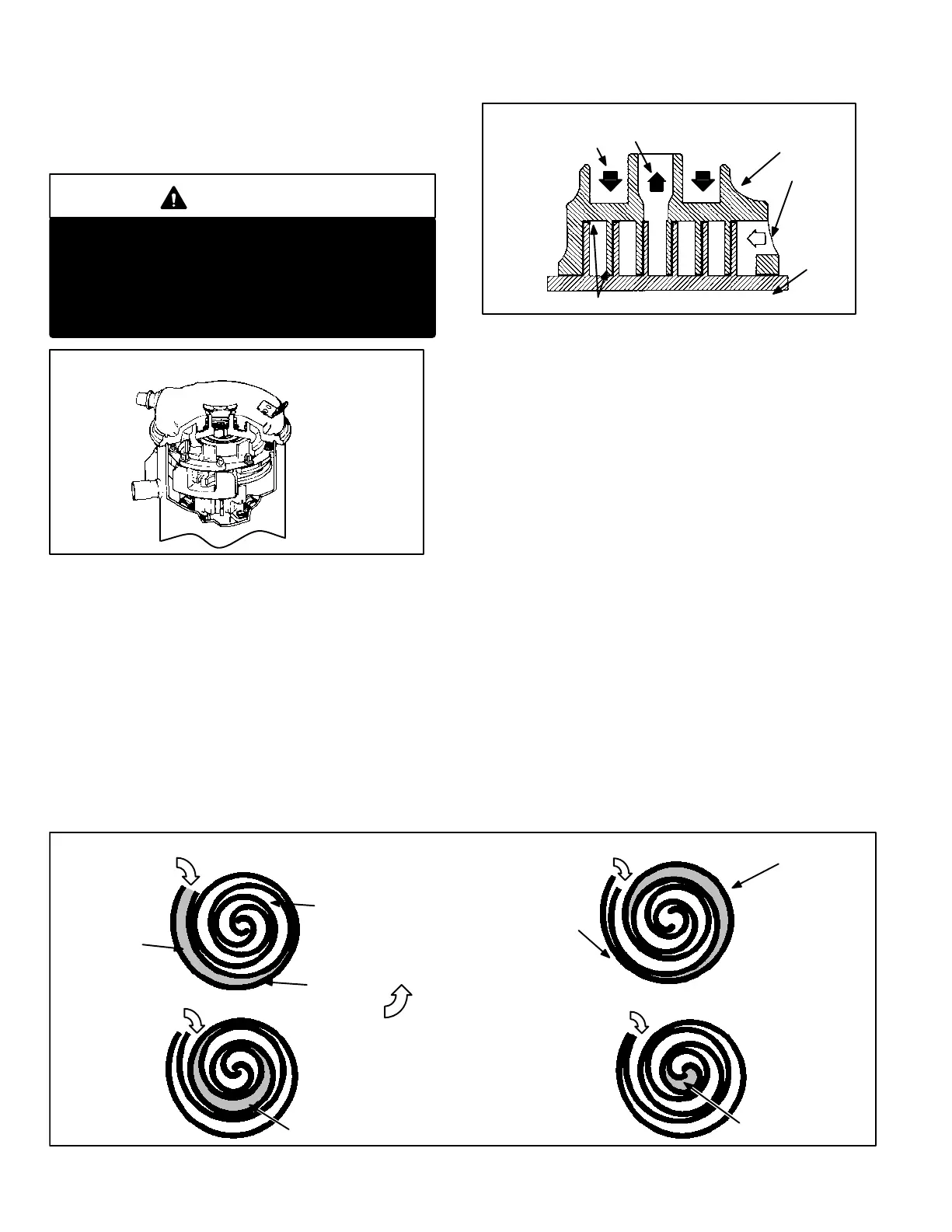
The counterclockwise orbiting scroll draws gas into the outer
crescent shaped gas pocket created by the two scrolls (fig-
ure (figure 14 − 1). The centrifugal action of the orbiting scroll
seals off the flanks of the scrolls (figure 14 − 2). As the orbit-
ing motion continues, the gas is forced toward the center of
the scroll and the gas pocket becomes compressed (figure
14 − 3). When the compressed gas reaches the center, it is
discharged vertically into a chamber and discharge port in
the top of the compressor (figure 12). The discharge pres-
sure forcing down on the top scroll helps seal off the upper
and lower edges (tips) of the scrolls (figure 13). During a
single orbit, several pockets of gas are compressed simulta-
neously providing smooth continuous compression.
The scroll compressor is tolerant to the effects of liquid re-
turn. If liquid enters the scrolls, the orbiting scroll is allowed
to separate from the stationary scroll. Continued slugging of
liquid will cause damage to the scroll and replacement will
be necessary. The liquid is worked toward the center of the
scroll and is discharged. If the compressor is replaced, con-
ventional Lennox cleanup practices must be used.
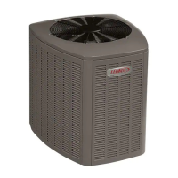
2−Condenser Fan
All 12GCS/CHP units use single phase condenser fans. Spec-
ifications for the condenser fans are at the front of this manual.
See table of contents.
FIGURE 14
1
SUCTION
POCKET
SUCTION
ORBITING
SCROLL
STATIONARY
SCROLL
2
SUCTION
INTERMEDIATE PRESSURE
GAS
CRECENT SHAPED
GAS POCKET
FLANKS SEALED
BY CENTRIFIGUAL FORCE
MOVEMENT OF ORBIT
3
SUCTION
HIGH PRESURE GAS
4
SUCTION
DISCHARGE
POCKET
 Loading...