Page 21
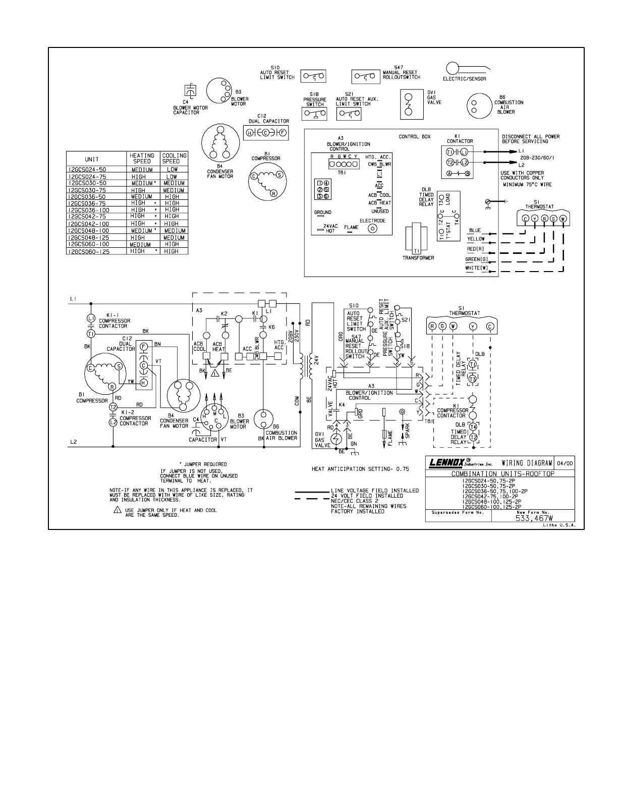
B−12GCS−024/060−2−P
Cooling
1− Cooling demand initiates at Y1 in the indoor thermo-
stat.
2− 24VAC from Y1 energizes time delay DL8, which ener-
gizes compressor contactor K1 if 5−minute delay has
been satisfied (DL8 is an optional component. If unit is
not equipped with DL8, 24VAC will go straight to K1.)
3− K1−1 and K1−2 close energizing compressor B1 and
outdoor fan motor B4.
4− Compressor B1 and outdoor fan B4 begin immediate
operation. Evaporator blower B3 begins after 5 second
delay.
5− When cool demand is satisfied, "Y1" in the indoor ther-
mostat de−energizes K1 contactor. K1−1 and K1−2 open
de−energizing compressor B1 and outdoor fan B4.
Evaporator blower B3 de−energizes after 90 second
delay.
Heating
1− Heating demand initiates at "W1" in the indoor thermo-
stat.
2− Assuming all safety circuits are closed, A3 energizes
the combustion air inducer blower B6. When the N.O.
combustion air inducer prove switch closes, a prepurge
period of 30 seconds will follow.
3− Ignition control A3 begins spark and energizes the gas
valve for 10 seconds.
4− When flame is sensed, spark stops.
5− After 30 seconds blower control A3 energizes evapo-
rator blower B3.
6− When heat demand is satisfied, "W1" in the indoor ther-
mostat de−energizes control A3 which de−energizes
the gas valve and combustion air inducer blower B6.
Evaporator blower B3 runs for a designated period of
120 seconds.
 Loading...