Page 30
The constant torque ECM (electronically commutated motor)
communicates with the air handler control via 24VAC inputs. It
is programmed to provide a constant level of torque (current /
power) to the motor. This is a multi-tap motor with the ability to
have 1 to 5 programmed levels of torque (see table 4). Each
value equals a specific amount of torque to create the proper
amount of airflow for each system demand. This value is spe
cific to model and size system.
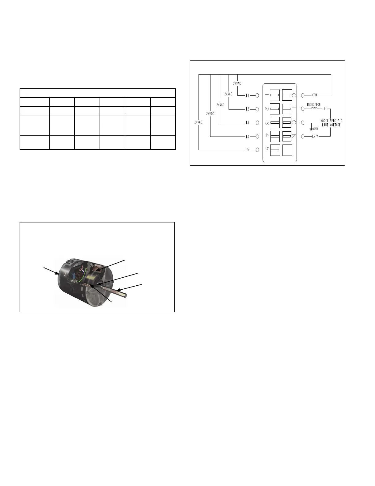
TABLE 4
TAP SETTINGS
Parameter Tap 1 Tap 2 Tap 3 Tap 4 Tap 5
OFF-Delay 0 45 45 45 45
Torque
(oz. ft)
(Se)
25.73 37.96 47.38 50.51 57.73
% of full
output
32.16 47.45 59.22 63.14 72.16
Each tap can have a unique amount of torque programmed
for a specific purpose. For example, switching from Tap 1 to
Tap 2 may increase the airflow, but not necessarily at a spe
cific interval like changing from low to medium low speed on
a PSC motor.
Internal components are shown in figure 14. The stator wind
ings are split into three poles which are electrically connected
to the controller. This arrangement allows motor windings to
turn on and off in sequence by the controller.
STATOR
(WINDINGS)
OUTPUT
SHAFT
BEARING
ROTOR
CONTROLLER
BLOWER MOTOR COMPONENTS
FIGURE 14.
The controller uses sensing devices to sense what position
the rotor is in at any given time. By sensing the position of the
rotor and then switching the motor windings on and off in se
quence, the rotor shaft turns the blower.
Operation
The 230VAC voltage connections to the motor are labeled
L, G and N.
230VAC L = L1 115VAC, G = Ground, N = L2 115VAC
The 230VAC is connected to the motor at all times. This
voltage operates the internal electronics and drives the mo
tor. In addition, the motor requires a low voltage to operate.
The low voltage to the motor is delivered to taps 1-5 and the
(C) terminal from the control relay. The motor accepts a
communication signal of 24VAC on these taps. Instead of
energizing a motor speed (winding) on a PSC motor for
each demand (heat cool, constant fan); the communication
voltage directs the motor to operate at the torque value
stored for each tap.
VOLTAGE CONNECTIONS
FIGURE 15.
During each demand, the fan motor will maintain the selec
ted torque during changes in the systems external static
pressure (ESP) (constant torque). If ESP increases the mo
tor will use more power (current) to maintain torque. The
motor has a programmed limit of operation to protect itself
from damage, due to the energy it must use to maintain
torque at high external static pressures. If the systems max
imum total ESP is exceeded, torque will not be maintained,
however the motor will deliver as much torque as possible,
without causing damage to itself.
Constant torque allows the fan motor to maintain the torque
(current) delivered to the motor when ESP is higher than re
commended and/or changes during system operation.
ESP (the resistance to the movement of air) is increased
when duct work is undersized, poorly constructed and/or
full or dirt or debris. ESP can increase during system opera
tion when dirt builds up on the air distribution systems com
ponents, especially the filter, and when customers close or
block grilles and registers. When torque is maintained, air
flow does not decrease as fast as it would on a PSC motor
system. This decreases the effect ESP has on loss of air
flow, providing better system performance and efficiency
within the limits of the motor design.
The fan motor has no programmable (On) delays but mul
tiple (Off) delays (see table 4) are programmed into the mo
tor. The off delay is programmed into the motor and can not
be adjusted.
Installation
It is recommended that the electrical connections on the
ECM be facing down or between the 4 and 8 O-clock posi
tion, and a drip loop formed out of the wiring harness leav
ing the motor. This is to prevent any moisture or water that
may get into the motor area from running into the connect
ors where it could cause damage to the control.
 Loading...