Page 5
NOTE – Maximum lifts are dependent on total length,
number of elbows, etc. that contribute to total pressure
drop.
• Maximum length vapor riser = 60 feet.
• Up to 50 Linear Feet: Use rated line sizes listed in table
1.
• Between 51 and 150 Linear Feet: Crankcase heater
and nonbleed port TXV factory installed. No additional
components required. Vertical vapor riser must be sized
to the vapor riser listed in the table 2 on systems with
line sets longer than 51 feet. Use tables 2 and 3 to de-
termine the correct liquid and vapor line sizes.
• Over 150 Linear Feet: not recommended.
• Additional oil is not required for systems with line lengths
up to 150 feet.
SUCTION TRAPS
For systems with the outdoor unit 5 - 60 feet above the
indoor unit, one trap must be installed at the bottom of the
suction riser.
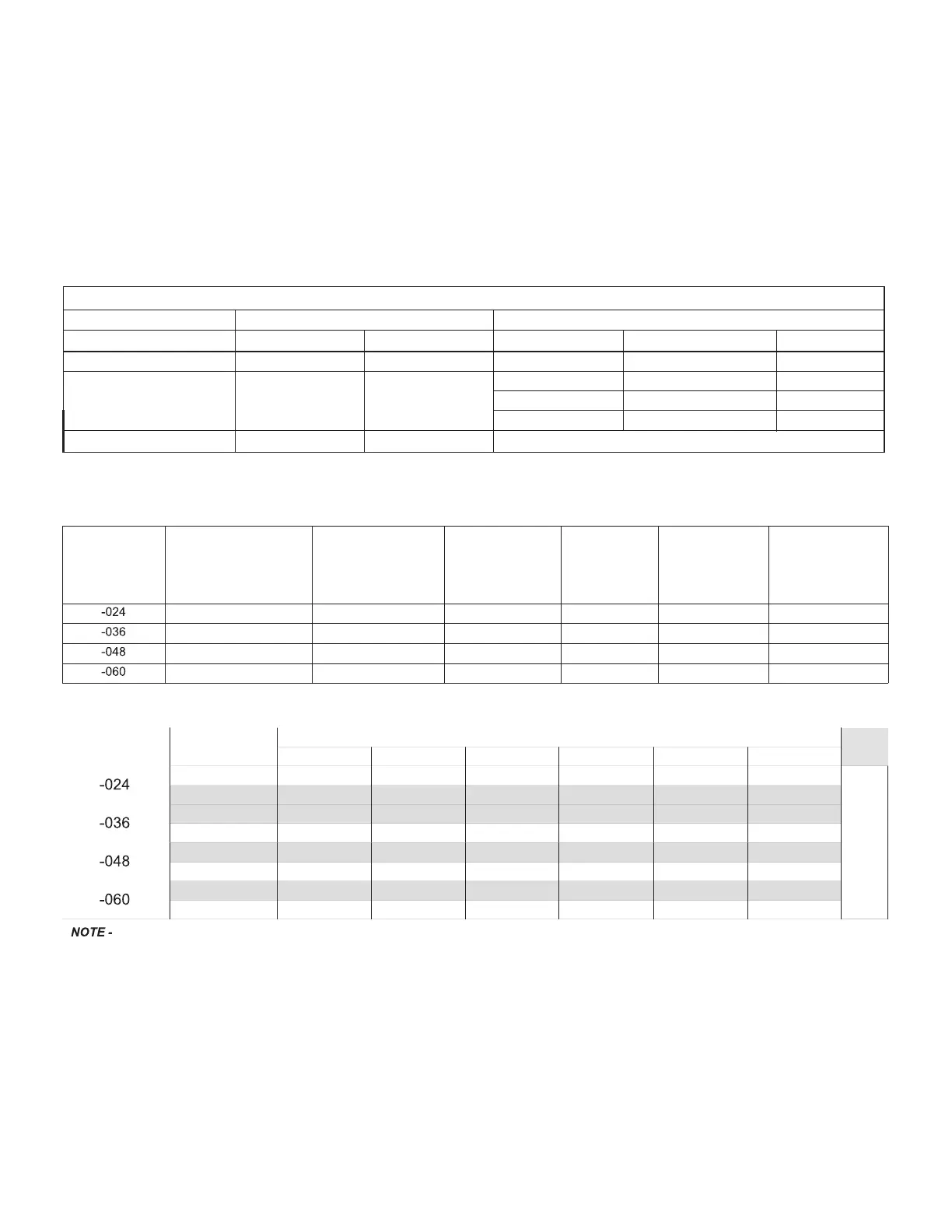
TABLE 2. Standard Refrigerant Line Set – Up to 50 Linear Feet in Length
Inches (mm)
Valve Size Connections Recommended Line Sets
EL22XPV*
Liquid Line Suction Line L15 Line Set Model Line Set Length Catalog Number
-024 3/8” (10 mm) 3/4” (19 mm) L15-41-20 20 feet (6.1 m) 89J56
-036
-048
3/8” (10 mm) 7/8” (22 mm)
L15-65-30
30 feet (12.2 m)
89J57
L15-65-40
L15-65-50
40 feet (15.2 m)
50 feet (15.2 m)
89J58
89J59
-060 3/8” (10 mm) 1-1/8” (29 mm) ** Field-fabricated
* Applicable to all minor revision numbers unless otherwise specified.
** Some applications may require a field-provided 1-1/8” to 7/8” adapter.
TABLE 3. EL22XPV Line Set Guidelines – 51 to 150 Linear Feet in Length
Model
Maximum Total
Equivalent Length (ft)
Maximum Linear
(actual) Length (ft)
Maximum Suction
Riser (ft)
Maximum
Linear Liquid
Lift (ft)
Preferred
Suction Line
Sizes for
Horizontal
Runs
Required Suction
Riser Size
180 150 60 60 7/8” 5/8”
180 150 60 60 7/8” 3/4”
180 150 60 60 7/8” 7/8”
180 150 60 60 7/8” 7/8”
TABLE 4. Liquid Line Diameter Selection Table
Unit Line Size
Total Linear Length (feet)
25 50 75 100 125 150
5/16”
25
50 55 48 40 33
Max. Elevation
(ft)
3/8”
25
50 60 60 60 60
3/8”
25
50 60 56 51 45
1/2”
25
50 60 60 60 60
3/8”
25
50 50 41 31 22
1/2”
25
50 60 60 60 60
3/8”
25
50 36 22 8 NR
1/2”
25
50 60 60 60 59
Shaded rows indicate rated liquid line size
A. Find your unit on the left side of the table.
B. Start with the rated liquid line size (shaded row) on the outdoor unit
C. Select the actual To tal Linear Length of your system shown at the top of the table.
D. The elevation listed in the table is the maximum allowed for the liquid line listed.
E. Select or consider the larger liquid line size shown in the table if the elevation does not meet your requirements.
NOTE - For new or replacement line set installation, refer to Service and Application Note - Corp. 9112-L4 (C-91-4).
 Loading...