Page 15
8 − K9 Isolation (Heat) Relay
Q" Models Only
Fan timing control (A28) with part number 79J65 con
tains a singlepole, singlethrow isolation relay (K9).
When there is a heat demand through W1, K9 is ener
gized closing the normally open contacts K91 in the
ignition circuit. The addition of an isolation relay in the
W1 circuit will eliminate electrical noise feeding from the
electronic thermostat back to the electronic ignition
control.
9 − K109 Accessory Relay V" Models Only
G21V−5 to −8 & GSR21V−10 to −15
A singlepole, singlethrow accessory relay is located inside
the control box to provide power to additional accessories
which may be used with the G21V / GSR21V.
10 − VSP1 Blower Control Board (A24)
V" Models Only G21V−1 to −3 &
GSR21V−1 to −9 (Figure 9)
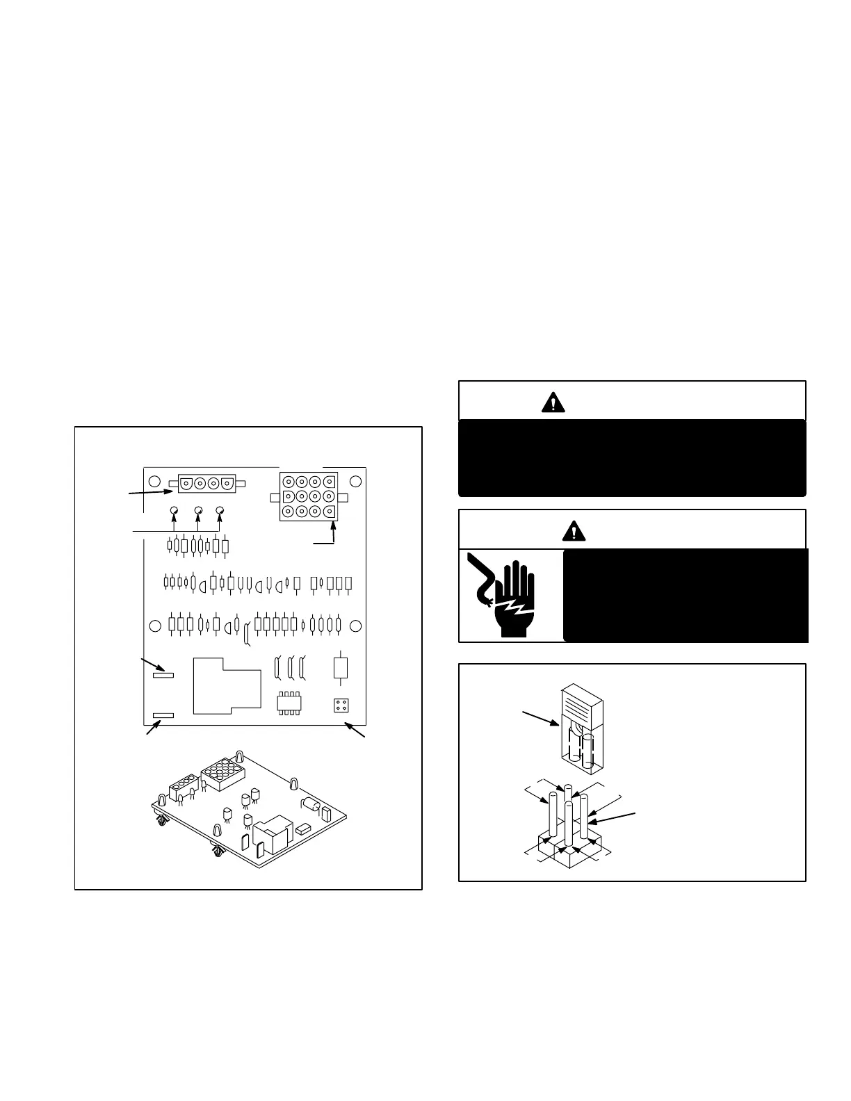
FANOFF
TIMING PINS
VSP1 BLOWER CONTROL BOARD (A24)
L1
ACC
DS3 DS2 DS1
120V
ACCESSORY
TERMINAL
L1 LINE
VOLTAGE
J73
VSP1 CONTROL
PLUG
J46
OUTPUT
PLUG
210
90
150
270
FRONT VIEW
12
1
3
69
1
4
DIAGNOSTIC
LEDS
FIGURE 9
The VSP1 (A24), a printed circuit board located in the con
trol box, serves four primary functions:
1− Controls blower timings during heating to accommo
date the required initial heat−up and cool−down times of
the heat exchanger.
2− Senses limit trip condition and turns on the blower.
3− Controls the accessory relay.
4− Interfaces the 24VAC thermostat with the blower.
When operating in heating mode, VSP1 controls the blower
and monitors limit and gas valve operation. The VSP1 con
trols the fanon" and fanoff" timings. Fanon timings are
preset and non adjustable. Fanoff timings are adjustable.
Fanon timing is the amount of time the unit operates before
the blower is started. This period allows for heat exchanger
warmup. The fanon timing is preset at 45 seconds and is
not adjustable.
FanOff timings (time that blower operates after heating
demand has been satisfied) are determined by the ar
rangement of a jumper on the VSP1 board. To adjust fanoff
timings, gently disconnect jumper and reposition it across
pins corresponding with new timing (see figure 10). The
fanoff timing is factory set at 270 seconds.
IMPORTANT
If fanoff time is too low, residual heat in heat ex
changer may cause primary limit S10 to trip result
ing in frequent cycling of blower. If this occurs, ad
just blower to longer time setting.
DANGER
Shock Hazard. VSP1 fan control is
connected to line voltage. Discon
nect power to unit before changing
pin timings. Can cause personal
injury or control damage.
FANOFF TIME ADJUSTMENT
270
210
150 90
To adjust fan−off timings:
Remove jumper from VSP1 and se
lect one of the other pin combina
tions to achieve the desired time.
TIMING
JUMPER
TIMING PINS (seconds)
Leave jumper off to achieve
330 second fan−off timing.
Fanoff timing is factory
set at 270 seconds
FIGURE 10
The VSP1 includes a 120 VAC accessory terminal. The ter
minal is wired directly to terminal block TB2 and powers the
accessory connection on the terminal block. The terminal
is energized when the blower is running. It can be used for
any desired accessory equipment such as an electronic air
cleaner or humidifier.
 Loading...
