Page 16
VSP1 provides an interface between the 24VAC indoor
thermostat signal and the direct current digital signal to the
blower motor. The control is responsible for energizing the
blower motor in response to thermostat demand and for
converting thermostat demand from 24VAC to 24VAC half
rectified (DC pulse) see figure 11. The motor controller (in
side the blower motor) is responsible for regulating blower
speed to maintain the desired CFM.
PIN 4 − 1217VDC INPUT
FROM HUMIDITY
CNTRL. TERM DS or
24VAC FROM TSTAT
TERMINAL Y2 IF CCB
OR HARMONY IS NOT
USED. PWM SIGNAL
FROM HARMONY.
FIGURE 11
VSP1 BLOWER CONTROL BOARD (A24)
PIN 1 − 24VAC COMMON
PIN 3 − 24VAC POWER TO
TSTAT
PIN 2 − 24VAC INPUT FROM
TSTAT TERM G
PIN 5 − OUTPUT SIGNAL
CONFIRMING HEATING
BLOWER SIGNAL
J73 Inputs
J46
Outputs
J73
Wires from J46 connect directly to indoor blower B3 jack J49. Volt
age on pins 2 and 3 are halfrectified AC (DC pulse). Measured volt
age will vary depending on the type of meter used.
J46
PIN 1 − Common
PIN 2 − 24VAC 1/2 rectified ON/OFF
PIN 3 − 24VAC 1/2 rectified HEAT
PIN 4 − 12−17VDC (Hi/Low) if CCB1 is used,
21VAC if CCB or Harmony is not used.
PWM signal if Harmony is used.
VOLTAGES INTO VSP1
VOLTAGES FROM VSP1 TO ELECTRONICALLY
CONTROLLED BLOWER MOTOR
34 volts
−34 volts
0 volts
Voltage across J73 pins 8 to 1 and 3 to 1 is 24VAC as shown here.
Refer to unit wiring diagram.
Voltage across J46 pins 2 to 1 and 3 to 1 is halfrectified AC as shown here.
Refer to unit wiring diagram.
Voltage across J73 pins 4 to 1 is approximately
1217VDC (straight voltage) if CCB is used. A PWM signal if Harmony is used.
If CCB or Harmony is not used, pin 4 to 1 voltage is 21VAC.
Approx.
34 volts
0 volts
Voltage across J46 pins 4 to 1, is approximately 1217VDC if CCB is used. If CCB or Har
mony is not used, pin 4 to 1 voltage is approximately 21VAC. A PWM signal if Harmony is
used.
24VAC @ 60Hz.
24VAC HalfRectified (DC Pulse)
@ 60Hz.
DS3
DS2
DS1
210
90
150
270
ACC
L1
1
2
3
4
PIN 6 − 24VAC INPUT FROM
TSTAT TERM W2
PIN 7 − 24VAC INPUT SIGNAL
FROM EXTERNAL LIMIT
PIN 8 − 24VAC POWER FOR
VSP1
PIN 9 − 24VAC INPUT FROM
GAS VALVE
PIN 10 − 24VAC OUTPUT FROM
VSP1 TO IGNITION
CONTROL A3
PIN 11 − 24VAC INPUT FROM
FAN LIMIT CONTROL
PIN 12 − 24VAC INPUT FROM
FAN LIMIT CONTROL
13
6
9
12
IMPORTANT
24 VAC half wave rectified (DC pulse), when mea
sured with a meter, may appear as a lower or high
er voltage depending on the make of the meter.
Rather than attempting to measure the output
voltage of A24, see G21V/GSR21V V" BLOWER
AND VSP1 BLOWER CONTROL BOARD TROU
BLESHOOTING FLOW CHART in the TROUBLE
SHOOTING section of this manual.
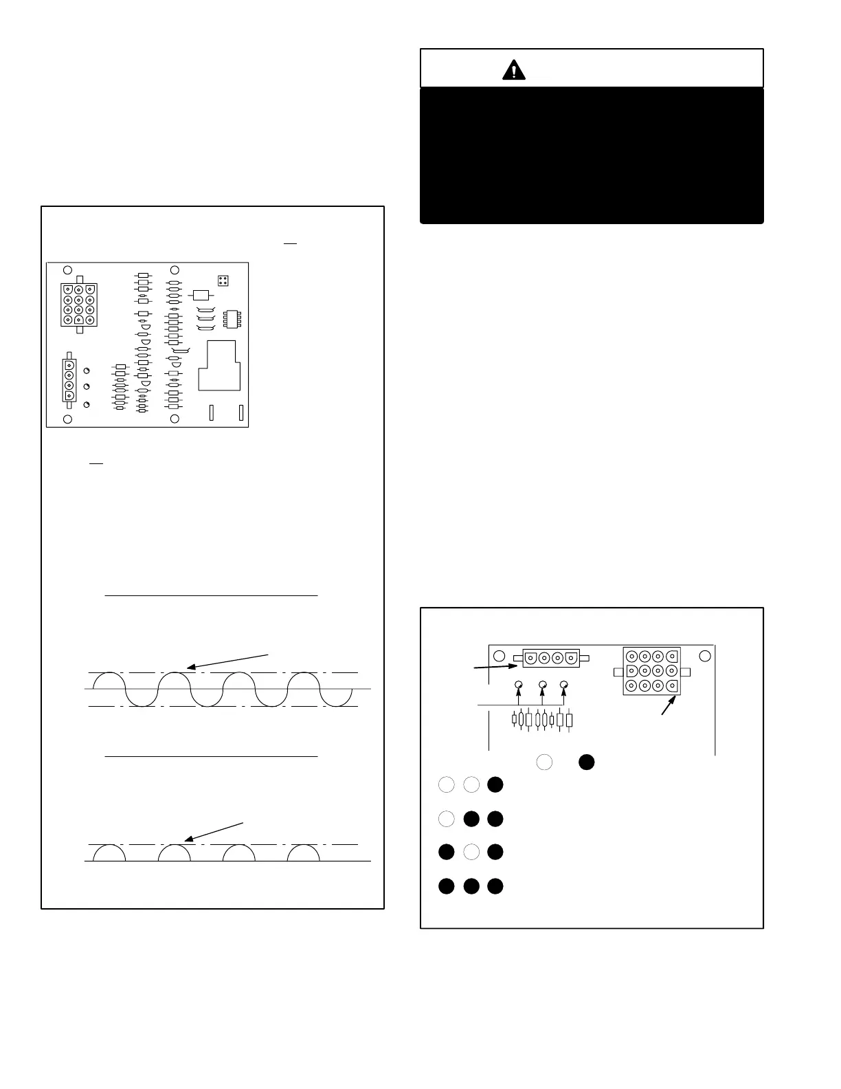
Diagnostic LED Lights
Three diagnostic LED lights are provided on the control for
troubleshooting. The three lights DS1, DS2 and DS3 (fig
ure 12) are on/off," hi speed heat" and high speed cool."
In the heating and cooling mode, the on/off LED (DS1) is lit
indicating the blower is operating on low speed heat/cool
tap. It is lit whenever a 24VAC thermostat demand is sup
plied to the control (jackplug JP73 pin 2). When the hi
speed heat"(DS2) and the on/off (DS1) LED are both lit the
blower is operating on high speed heating tap (1217VDC
from CCB1 terminal DS or 24VAC from Y2 if CCB1 is not
used). During dehumidification mode, the CCB1 turns off
the DS output and the blower operates on low speed heat/
cool tap. When the high speed cool" (DS3) and the on/off"
(DS1) LED are both lit the blower is operating on high
speed cool tap.
If the unit is switched from a heating demand to a 2nd stage
cooling demand, all three lights (DS1, DS2 and DS3) may
be energized for a short time. During this period, blower
operates on high speed heating tap.
VSP1 BLOWER CONTROL BOARD (A24)
FIGURE 12
DS3 DS2 DS1
DIAGNOSTIC
LEDS
J73
VSP1 CONTROL
PLUG INPUTS
J46
OUTPUT
PLUG
FRONT VIEW (PARTIAL)
DS3 DS2 DS1
DS3 DS2 DS1
DS3 DS2 DS1
UNIT OPERATING ON LOW
SPEED
HEAT/COOL TAP
UNIT OPERATING ON HIGH SPEED HEAT TAP
UNIT OPERATING ON HIGH SPEED COOL TAP
NOT LIT LIT
Any other combination could indicate possible trouble with the
VSP1 refer to TROUBLESHOOTING section of this manual
3
1
69
12
1
DS3 DS2 DS1
UNIT SWITCHED FROM HEATING DEMAND TO
2nd STAGE COOLINGUNIT OPERATES ON
HIGH SPEED HEAT TAP MOMENTARILY
 Loading...
