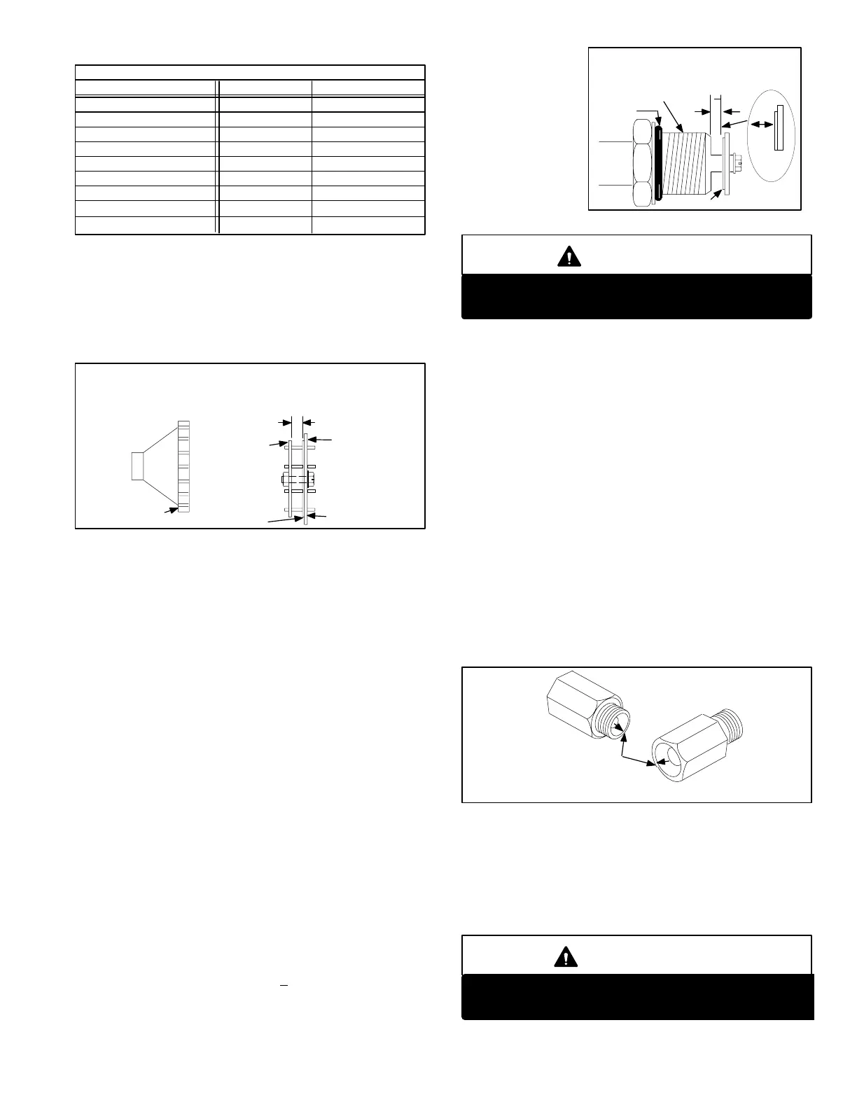
GAS FLAPPER VALVE
REQUIRED CLEARANCE
VALVE BODY
FLAPPER
ORING
REQUIRED CLEARANCE
0.024" + 0.003"
FIGURE 74
Page 53
TABLE 17
AIR FLAPPER VALVE CLEARANCES (In.)
Unit Natural L.P.G.
G2160
G2140
G2180
G21100
GSR2150
GSR2180
GSR21100
.031
.035
.0425 or .045
.037
.035
.0425 or .045
.039
.035
.0425 or .045
.040
.035
.0425 or .045
.037
.039
G21Q100−5,−6,−7,−8
.040 .040
G21V−7,−8
.040 .040
6 − When placing a new or old valve back into the unit, start
all eight screws in place by hand. Tighten screws even
ly to a maximum of 15 in./lbs. Do not overtighten
screws; if threads are damaged the entire valve body
will have to be replaced. All eight screws must be in
place for proper operation
CLEARANCES ARE SUBJECT TO CHANGE. REFER TO LENNOX
REPAIR PARTS OR SERVICE AND APPLICATION NOTES HEATING
TAB FOR LATEST INFORMATION.
COVER
PLATE
VALVE BODY
BACK
PLATE
FLAPPER
STAMP
40,50, 60, 80 AIR FLAPPER VALVE CLEARANCE
CLEARANCE
FIGURE 73
O − Checking the Gas Flapper Valve
1 − Using a plumber’s basin wrench, disconnect union at
bottom of expansion tank and remove entire gas flap
per valve, nipple and elbow assembly as one piece. It
is not recommended to remove elbow and nipple from
flapper unless the valve is being replaced. Use care
not to damage oring when handling valve out of unit.
DO NOT DROP.
2 − Do not turn or remove center screw of valve assembly.
Visually inspect the flapper. The flapper may be dished
or curved on new units, this is normal. In units with run
in" time, the flapper will be flat. If the flapper is torn,
creased or has uneven (frayed) edges, the valve as
sembly must be replaced.
3 − Check for free movement of the flapper over the
spacer. Use a feeler gauge blade to carefully move the
flapper between the plates. Be sure the flapper is not
trapped between the spacer and the other clearance
plate. If the flapper does not move freely or is trapped
under the spacer, the valve assembly must be re
placed.
4 − Check for the required clearance between the flapper
and valve body. Required clearance values for
G21/GSR21 units are 0.024 + 0.003 in. Use a feeler
gauge, starting small and working up to the clearance di
mensions until the gauge is just about snug. Do not force
gauge. Check
clearance around
the valve in sev
eral places. If the
valve is out of the
required clear
ance dimension
given in figure at
any point around
the valve, it must
be replaced.
Do not force feeler gauge between flapper and
valve body. Damage to flapper material will occur.
WARNING
5 − When placing a new or old valve back into the unit, use
care not to damage the oring. DO NOT USE PIPE SEAL
ERS ON THE FLAPPER VALVE THREADS.
P − Checking Gas Orifice
1 − With gas flapper valve assembly removed, use a flash
light to check for blockage of the orifice in the manifold.
To remove the orifice, most units use a 1/2 inch shallow
socket with an extension.
2 − Check the orifice drill size for the unit as given in the
Service and Application notes. Make sure orifice diam
eter matches the drill size stamped on the orifice. If the
orifice is incorrect it must be replaced.
3 − Refer to figure for the physical characteristics of the ori
fice. The surface must be flat and the orifice opening
must not be chamfered. The orifice taper must be cen
tered and not recessed. G21/GSR21 units use a
doubleconed orifice to improve operating characteris
tics. If any defects are found the orifice must be re
placed.
G21/GSR21 SERIES ORIFICE
CHARACTERISTICS
ORIFICE MUST BE TAPERED ON BOTH SIDES
ORIFICE TAPER MUST BE CEN
TERED. RIDGE MUST BE EQUAL
AROUND PERIMETER AND TA
PER MUST START AT LEADING
EDGE (NOT RECESSED)
FIGURE 75
4 − Standard atmospheric burner orifices or orifice blanks
cannot be used as replacements for the G21/ GSR21.
Only replacement orifices supplied through Lennox
should be used.
5 − When threading the orifice into the manifold use a sock
et to hold threads beyond end of socket.
IMPORTANT
To avoid cross threading, carefully align threads by
hand turning socket extension until orifice is in place.
 Loading...
