Page 17
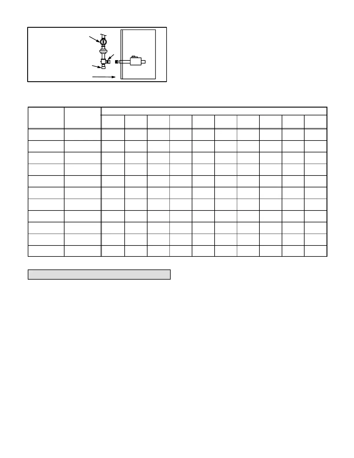
FIGURE 15
MANUAL MAIN SHUT-OFF
VALVE WILL NOT
HOLD NORMAL
TEST PRESSURE
CAP
FURNACE
ISOLATE
GAS
VALVE
CAP
The furnace must be isolated from the gas supply system
by closing its individual manual shutoff valve during any
pressure testing of the gas supply system at pressures
equal to or greater than 1/2 psig (3.48 kPa).
TABLE 9
GAS PIPE CAPACITY - FT
3
/HR (kL/HR)
Nominal Internal
Length of Pipe-Feet(m)
Iron Pipe Size
-Inches(mm)
Diameter
-Inches(mm)
10
(3.048)
20
(6.096)
30
(9.144)
40
(12.192)
50
(15.240)
60
(18.288)
70
(21.336)
80
(24.384)
90
(27.432)
100
(30.480)
1/4
(6.35)
.364
(9.246)
43
(1.13)
29
(.82)
24
(.68)
20
(.57)
18
(.51)
16
(.45)
15
(.42)
14
(.40)
13
(.37)
12
(.34)
3/8
(9.53)
.493
(12.522)
95
(2.69)
65
(1.84)
52
(1.47)
45
(1.27)
40
(1.13)
36
(1.02)
33
(.73)
31
(.88)
29
(.82)
27
(.76)
1/2
(12.7)
.622
(17.799)
175
(4.96)
120
(3.40)
97
(2.75)
82
(2.32)
73
(2.07)
66
(1.87)
61
(1.73)
57
(1.61)
53
(1.50)
50
(1.42)
3/4
(19.05)
.824
(20.930)
360
(10.19)
250
(7.08)
200
(5.66)
170
(4.81)
151
(4.28)
138
(3.91)
125
(3.54)
118
(3.34)
110
(3.11)
103
(2.92)
1
(25.4)
1.049
(26.645)
680
919.25)
465
(13.17)
375
(10.62)
320
(9.06)
285
(8.07)
260
(7.36)
240
(6.80)
220
(6.23)
205
(5.80)
195
(5.52)
1-1/4
(31.75)
1.380
(35.052)
1400
(39.64)
950
(26.90)
770
(21.80)
660
(18.69)
580
(16.42)
530
(15.01)
490
(13.87)
460
(13.03)
430
(12.18)
400
(11.33)
1-1/2
(38.1)
1.610
(40.894)
2100
(59.46)
460
(41.34)
1180
(33.41)
990
(28.03)
900
(25.48)
810
(22.94)
750
(21.24)
690
(19.54)
650
(18.41)
620
(17.56)
2
(50.8)
2.067
(52.502)
3950
(111.85)
2750
(77.87)
2200
(62.30)
1900
(53.80)
1680
(47.57)
1520
(43.04)
1400
(39.64)
1300
(36.81)
1220
(34.55)
1150
(32.56)
2-1/2
(63.5)
2.469
(67.713)
6300
(178.39)
4350
(123.17)
3520
(99.67)
3000
(84.95
2650
(75.04)
2400
(67.96)
2250
(63.71)
2050
(58.05)
1950
(55.22)
1850
(52.38)
3
(76.2)
3.068
(77.927)
11000
(311.48)
7700
(218.03)
6250
(176.98)
5300
(150.07)
4750
(134.50)
4300
(121.76)
3900
(110.43)
3700
(104.77)
3450
(97.69)
3250
(92.03)
4
(101.6)
4.026
(102.260)
23000
(651.27)
15800
(447.39)
12800
(362.44)
10900
(308.64)
9700
(274.67)
8800
(249.18)
8100
(229.36)
7500
(212.37)
7200
(203.88)
6700
(189.72)
NOTE-Capacity given in cubic feet of gas per hour (kilo liters of gas per hour) and based on 0.60 specific gravity gas.
Electrical
A field makeup box is provided for line voltage wiring.
Line voltage wiring to unit is done through the J69 jack
from the field makeup box to plug P69 from the control
box. See figures 17 and 18 for makeup box installation.
Figure 19 shows thermostat designations for identifica
tion purposes. Refer to figure 20 for control box arrange
ment, 21 for a detail of the SureLight integrated control
board (SureLight control), figure 22 for schematic wiring
diagram and troubleshooting, and figure 23 for point to
point field wiring.
1 - Install field makeup box on either side, inside or out
of the cabinet. Wiring knockouts are provided in box
and cabinet. See figures 17 and 18.
2 - Remove cap from knockout in blower deck on the
same side as the installed makeup box.
3 - Electrically ground unit in accordance with local
codes or, in the absence of local codes, in accor
dance with the current National Electric Code (ANSI/
NFPA No. 70). The green ground wire is provided in
the field make-up box.
To ensure proper grounding of the furnace, two star
washers are included in the electrical makeup box
bag assembly. Place the star washer on securing
screw before installing the makeup box. Make sure
the star washer breaks the paint on the cabinet so
that the washer is touching metal. Unit is not properly
grounded if paint has not been removed by star
washer.
 Loading...