Page 16
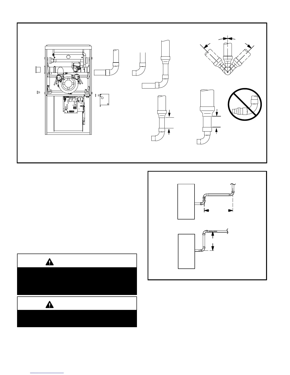
FIGURE 14
TYPICAL EXHAUST PIPE CONNECTIONS AND CONDENSATE TRAP INSTALLATION
IN UPFLOW DIRECT OR NON−DIRECT VENT APPLICATIONS
(Right−Hand Exit)
VENT PLUG
(Must be
glued in
place)
PLUG
*2" diameter street elbow provided.
CONDENSATE
TRAP
(Must be installed
on same side as
exhaust piping)
−135 with
3" OR 4" vent pipe
3" to 2" REDUCING ELBOW
(provided)
2"
−045, −070, or
−090 with
2−1/2", 3", or 4"
vent pipe
2"
TRANSITION
(use only if 4"
pipe is
required)
4"
2"
2"
2−1/2",
3", OR
4"
TRANSITION
2"
2"
−110 with
2−1/2", 3", OR 4"
vent pipe
*2"
TRANSITION
2−1/2",
3", OR
4"
2"
**2
45°
MAX
45°
MAX
SIDE VIEW
or
** Street elbow may be used on −045, −070 and −090.
−045, −070 or
−090 ONLY
−110 with 2"
vent pipe
2 − All horizontal runs of exhaust pipe must slope back to-
ward unit. A minimum of 1/4" (6mm) drop for each 12"
(305mm) of horizontal run is mandatory for drainage.
Horizontal runs of exhaust piping must be supported ev-
ery 5 feet (1.52m) using hangers.
NOTE − Exhaust piping should be checked carefully to
make sure there are no sags or low spots.
3 − On the opposite side of the cabinet, glue the provided
2" ABS vent plug into the unused ABS flue collar with
ABS or all purpose solvent cement.
4 − Route piping to outside of structure. Continue with
installation following instructions given in piping ter-
mination section.
CAUTION
Do not discharge exhaust into an existing stack or
stack that also serves another gas appliance. If verti-
cal discharge through an existing unused stack is re-
quired, insert PVC pipe inside the stack until the end
is even with the top or outlet end of the metal stack.
CAUTION
The exhaust vent pipe operates under positive pres-
sure and must be completely sealed to prevent leak-
age of combustion products into the living space.
FIGURE 15
Exhaust Pipe Offset
12" Min.*
12" Min.
Upflow Application
Rooftop Termination
Upflow Application
Side Wall Termination
*A minimum of 1/4" (6mm) drop for each 12" (305mm) of horizontal run is
mandatory for drainage

 Loading...