Page 17
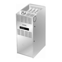
TYPICAL AIR INTAKE PIPE CONNECTIONS
UPFLOW DIRECT VENT APPLICATIONS
(Right−Hand Exit Shown)
FIGURE 16
PLUG
(Must be
glued in
place)
2*
2
*Pipe length must be limited
to 4" in −135 applications.
−24B−045
−24B−070
−36B−070
−36C−090
−36C−090H
−48C−090
−48C−110
48C−110H
−60C−110
−24B−045
−24B−070
−36B−070
−36C−090
−36C−090H
−48C−090
−48C−110*
−48C−110H*
−60C−110*
−24B−045
−24B−070
−36B−070
−36C−090
−36C−090H
−48C−090
−48C−110
−48C−110H
−60C−110
−60D−135*
2
2
2
*2"
*2
TRANSITION
2−1/2",
3" OR
4
TRANSITION
2−1/2",
3" OR
4
Intake Piping
The G43UF furnace may be installed in either direct vent
or non−direct vent applications. In non−direct vent ap-
plications, when intake air will be drawn into the furnace
from the surrounding space, the indoor air quality must be
considered and guidelines listed in Combustion, Dilution
and Ventilation Air section must be followed.
The G43UF unit is designed for either left−side or right−side
air intake connections. Intake air piping is independent of
exhaust piping.
Follow the next four steps when installing the unit in Direct
Vent applications, where combustion air is taken from
outdoors and flue gases are discharged outdoors. The
provided air intake screen must not be used in direct
vent applications.
1 − Use transition solvent cement to connect PVC pipe to
the ABS slip connector located on the side of the burn-
er box.
2 − Use a sheet metal screw to secure the intake pipe to
the connector, if desired. A pilot indentation is pro-
vided in the slip connector to assist in locating and
starting the fastener.
3 − Glue the provided 2" ABS plug into the unused ABS air
intake connector on the opposite side of the cabinet with
ABS all pupose cement.
4 − Route piping to outside of structure. Continue with
installation following instructions given in general
guide lines for piping terminations and in intake and
exhaust piping terminations for direct vent sections.
Refer to figure 16 for pipe sizes.
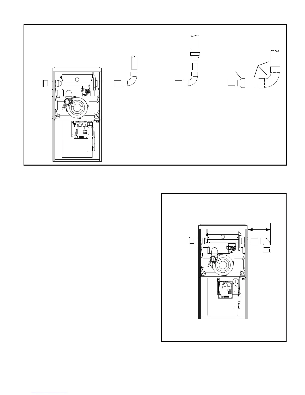
FIGURE 17
PLUG
(Must be
glued in
place)
TYPICAL AIR INTAKE PIPE CONNECTIONS
UPFLOW NON−DIRECT
VENT APPLICATIONS
(Right−Hand Exit Shown)
6 in. Max.
INTAKE
DEBRIS
SCREEN
(Provided)
NOTE − Debris screen and elbow may be rotated, so that
screen may be positioned to face forward, backward or
downward.

 Loading...