Page 29
G60UH Series
Integrated Control
G60UH units are equipped with a two−stage integrated
control. This control manages ignition timing and fan off
delays based on selections made using the control DIP
switches and jumpers. The control includes an internal
watchguard feature which automatically resets the ignition
control when it has been locked out. After one hour of con-
tinuous thermostat demand for heat, the watchguard will
break and remake thermostat demand to the furnace and
automatically reset the control to relight the furnace.
DIP Switch Settings
Switch 1 −− Thermostat Selection −− This unit may be used
with either a single−stage or two−stage thermostat. The
thermostat selection is made using a DIP switch which
must be properly positioned for the particular application.
The DIP switch is factory−positioned for use with a two−
stage thermostat. If a single−stage thermostat is to be used,
the DIP switch must be repositioned.
a − Select OFF" for two−stage heating operation con-
trolled by a two−stage heating thermostat (factory set-
ting);
b − Select ON" for two−stage heating operation con-
trolled by a single−stage heating thermostat. This set-
ting provides a timed delay before second−stage heat
is initiated.
Switch 2 −− Second Stage Delay (Used with Single−
Stage Thermostat Only) −− This switch is used to deter-
mine the second stage on delay when a single−stage ther-
mostat is being used. The switch is factory−set in the OFF
position, which provides a 10−minute delay before second−
stage heat is initiated. If the switch is toggled to the ON
position, it will provide a 15−minute delay before second−
stage heat is initiated. This switch is only activated when
the thermostat selector jumper is positioned for SINGLE−
stage thermostat use.
Switches 3 and 4 −− Heating Blower−Off Delay −− The
heating blower−on delay of 45 seconds is not adjustable.
The heating blower−off delay (time that the blower operates
after the heating demand has been satisfied) can be ad-
justed by moving switches 3 and 4 on the integrated con-
trol. The unit is shipped from the factory with a heating
blower−off delay of 90 seconds. The heating blower off
delay affects comfort and is adjustable to satisfy individual
applications. Adjust the blower off delay to achieve a sup-
ply air temperature between 90° and 110°F at the exact
moment that the blower is de−energized. Longer off delay
settings provide lower supply air temperatures; shorter set-
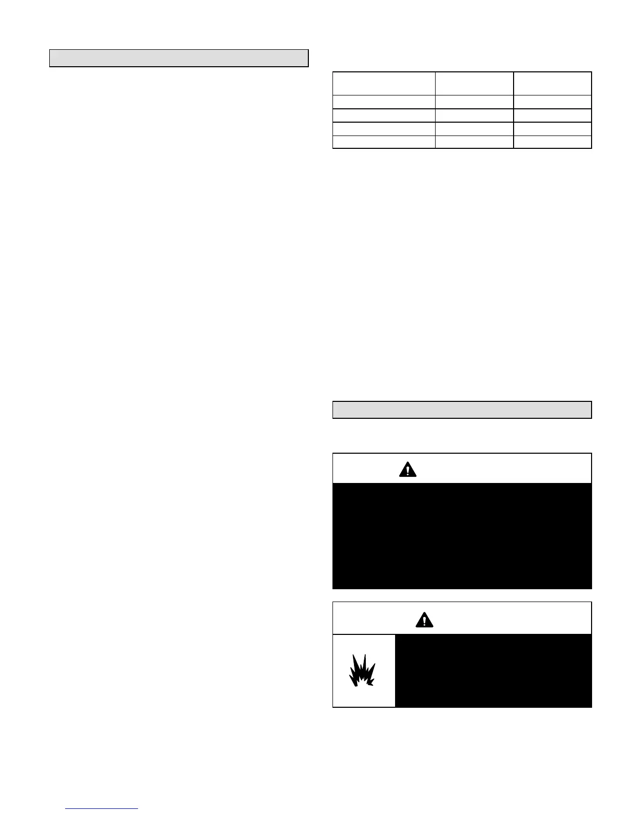
tings provide higher supply air temperatures.Table 11 pro-
vides the blower off timings that will result from different
switch settings.
TABLE 11
Heating Blower−Off Delay Switch Settings
Blower Off Delay
(Seconds)
Switch 3 Switch 4
60 Off On
90 Off Off
120 On Off
180 On On
Switch 5 −− Cooling Blower−Off Delay −− The cooling
blower−off delay (time that the blower operates after the
cooling demand has been satisfied) can be adjusted by
moving switch 5 on the integrated control. The switch is fac-
tory−set in the OFF position, which provides a cooling blow-
er−off delay of 45 seconds. If the switch is toggled to the ON
position, it will provide a 2−second cooling blower−off delay
On−Board Link W951
On−board link W951 is a clippable connection between ter-
minals R and O on the integrated control. W951 must be cut
when the furnace is installed in applications which include a
heat pump unit and a thermostat which features dual fuel
use. If the link is left intact, terminal O" will remain ener-
gized eliminating the HEAT MODE in the heat pump.
On−Board Link W915
On−board link W915 is a clippable connection between ter-
minals Y1 and Y2 on the integrated control. W915 must be
cut if two−stage cooling will be used. If the link is not cut the
outdoor unit will operate in second−stage cooling only.
Unit Start−Up
FOR YOUR SAFETY READ BEFORE LIGHTING
WARNING
Do not use this furnace if any part has been under-
water. A flood−damaged furnace is extremely dan-
gerous. Attempts to use the furnace can result in
fire or explosion. Immediately call a licensed pro-
fessional service technician (or equivalent) to in-
spect the furnace and to replace all gas controls,
control system parts, and electrical parts that have
been wet or to replace the furnace, if deemed neces-
sary.
WARNING
Danger of explosion. Can cause injury
or product or property damage. Should
the gas supply fail to shut off or if
overheating occurs, shut off the gas
valve to the furnace before shutting off
the electrical supply.

 Loading...


