Page 26
The gas valve is factory set and should not require adjust-
ment. All gas valves are factory regulated.
Manifold Adjustment Procedure:
1 − Connect a test gauge to manifold pressure tap on gas
valve. See figure 14 for tap location. Start unit and al-
low 5 minutes for unit to reach steady state.
2 − While waiting for the unit to stabilize, notice the flame.
Flame should be stable and should not lift from burner.
Natural gas should burn blue. L.P. gas should burn
mostly blue with some orange streaks.
3 − After allowing unit to stabilize for 5 minutes, record
manifold pressure.
NOTE−Shut unit off and remove manometer as soon as
an accurate reading has been obtained. Take care to re-
place pressure tap plug.
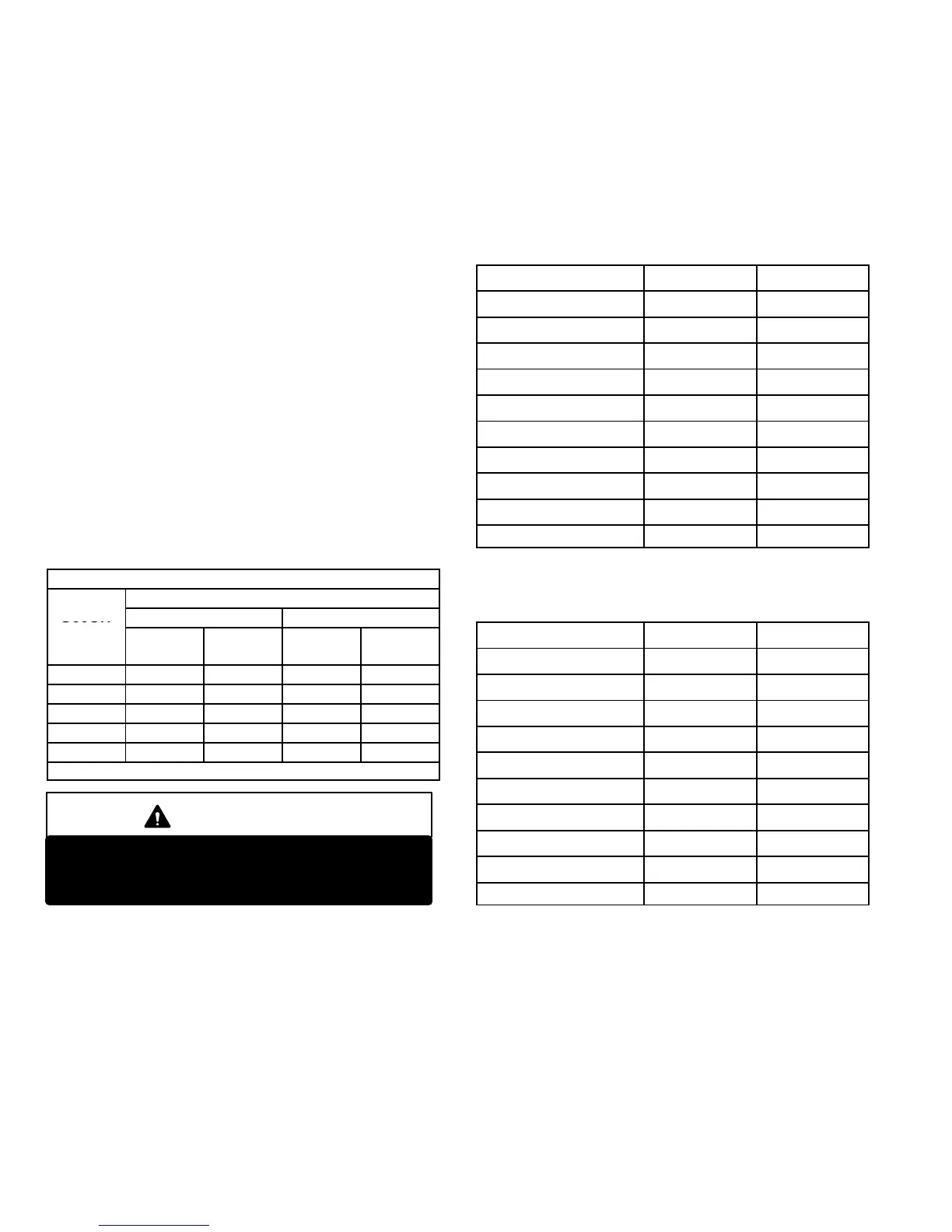
F− Proper Gas Flow (Approximate)
Furnace should operate at least 5 minutes before check-
ing gas flow. Determine time in seconds for two revolu-
tions of gas through the meter. (Two revolutions assures a
more accurate time.) Divide by two and compare to time
in table 16 below. If manifold pressure matches table 15
and rate is incorrect, check gas orifices for proper size and
restriction.
NOTE− To obtain accurate reading, shut off all other gas
appliances connected to meter.
TABLE 16
GAS METER CLOCKING CHART
Seconds for One Revolution
G60UH
Natural LP
Unit
1 cu ft
Dial
2 cu ft
Dial
1 cu ft
Dial
2 cu ft
DIAL
−45 82 164 205 410
−70 55 110 136 272
−90 41 82 102 204
−110 33 66 82 164
−135 27 54 68 136
Natural−1000 btu/cu ft LP−2500 btu/cu ft
IMPORTANT
For safety, shut unit off and remove manometer as
soon as an accurate reading has been obtained.
Take care to replace pressure tap plug.
G− Proper Combustion
Furnace should operate minimum 15 minutes with correct
manifold pressure and gas flow rate before checking com-
bustion. See sections E− and F−. Take combustion sample
beyond the flue outlet and compare to the tables below.
The maximum carbon monoxide reading should not ex-
ceed 100 ppm.
TABLE 17
High Heat
Unit
CO
2
%
For
Nat
CO
2
%
For
L.P.
G60UH−24A−045(X) 6.5 − 7.5 7.3 − 8.3
G60UH−24A−070 6.8 − 7.8 8.3 − 9.3
G60UH−36A−070(X) 7.2 − 8.2 8.0 − 9.0
G60UH−48B−070 7.2 − 8.2 8.0 − 9.0
G60UH−36B−090 7.5 − 8.5 8.5 − 9.5
G60UH−48B−090(X) 8.0 − 9.0 8.7 − 9.7
G60UH−36C−110 7.5 − 8.5 8.7 − 9.7
G60UH−48C−110 7.5 − 8.5 8.7 − 9.7
G60UH−60C−110(X) 7.3 − 8.3 8.5 − 9.5
G60UH−60D−135 7.5 − 8.5 8.5 − 9.5
TABLE 18
Low Heat
Unit
CO
2
%
For
Nat
CO
2
%
For
L.P.
G60UH−24A−045(X) 4.0 − 5.0 4.0 − 5.0
G60UH−24A−070 4.2 − 5.2 5.0 − 6.0
G60UH−36A−070(X) 4.2 − 5.2 5.0 − 6.0
G60UH−48B−070 4.2 − 5.2 5.0 − 6.0
G60UH−36B−090 4.7 − 5.7 5.0 − 6.0
G60UH−48B−090(X) 4.8 − 5.8 5.2 − 6.2
G60UH−36C−110 4.5 − 5.5 5.3 − 6.3
G60UH−48C−110 4.7 − 5.7 5.3 − 6.3
G60UH−60C−110(X) 4.5 − 5.5 5.5 − 6.5
G60UH−60D−135 4.7 − 5.7 5.5 − 6.5
 Loading...


