Page 25
IV−HEATING SYSTEM SERVICE CHECKS
A−C.S.A. Certification
All units are C.S.A. (formally A.G.A. and C.G.A. combined)
design certified without modifications. Refer to the
G60UH(X) Installation Instruction.
B−Gas Piping
CAUTION
If a flexible gas connector is required or allowed by
the authority that has jurisdiction, black iron pipe
shall be installed at the gas valve and extend outside
the furnace cabinet.
WARNING
Do not exceed 600 in−lbs (50 ft−lbs) torque when
attaching the gas piping to the gas valve.
Gas supply piping should not allow more than 0.5"W.C. drop
in pressure between gas meter and unit. Supply gas pipe
must not be smaller than unit gas connection.
Compounds used on gas piping threaded joints should be
resistant to action of liquefied petroleum gases.
C−Testing Gas Piping
IMPORTANT
In case emergency shutdown is required, turn off
the main shut-off valve and disconnect the main
power to unit. These controls should be properly
labeled by the installer.
When pressure testing gas lines, the gas valve must be dis-
connected and isolated. Gas valves can be damaged if
subjected to more than 0.5psig (14" W.C.). See figure 15.
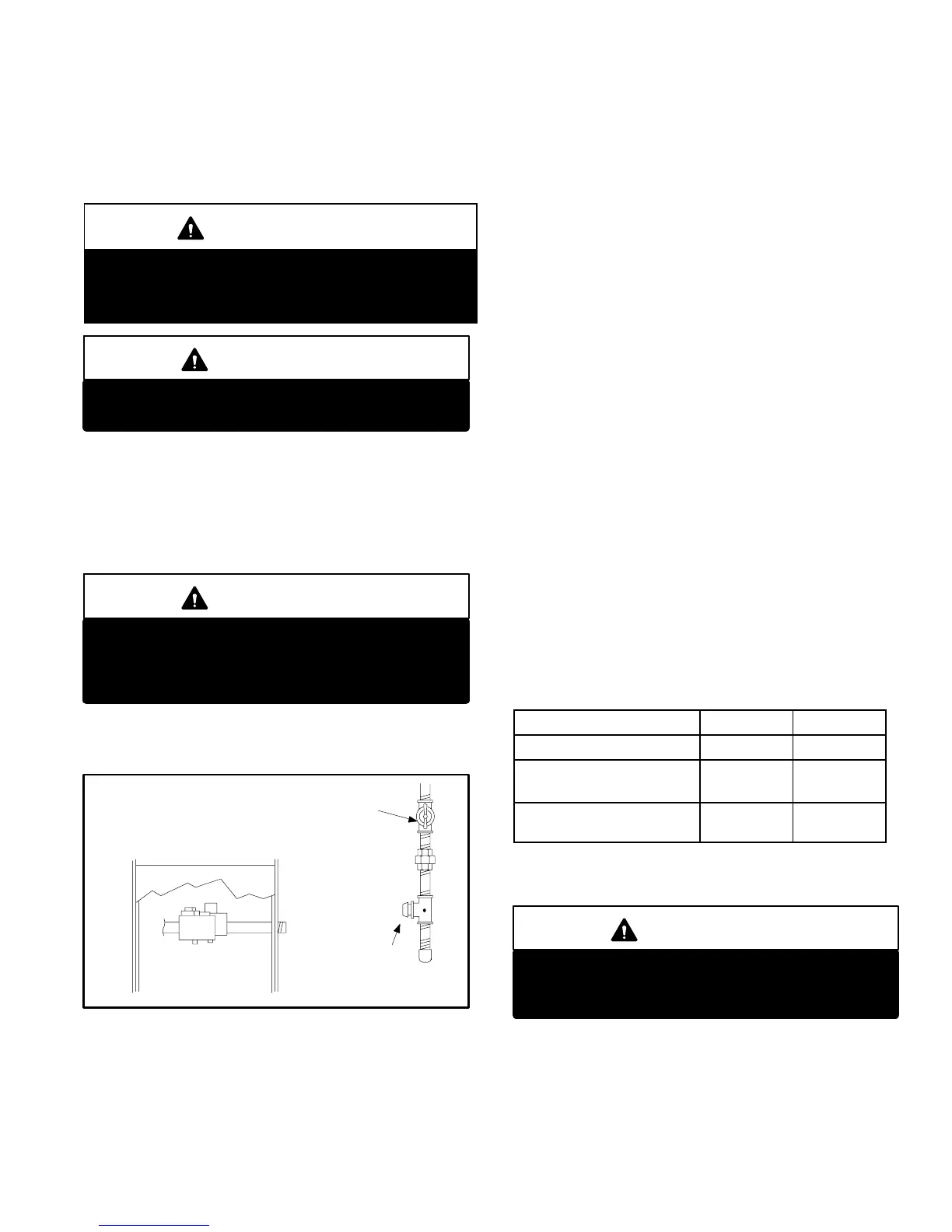
FIGURE 15
MANUAL MAIN SHUT−OFF VALVE
GAS VALVE
CAP
GAS PIPING TEST PROCEDURE
When checking piping connections for gas leaks, use pre-
ferred means. Kitchen detergents can cause harmful corro-
sion on various metals used in gas piping. Use of a specialty
Gas Leak Detector is strongly recommended. It is available
through Lennox under part number 31B2001. See Corp.
8411−L10, for further details.
Do not use matches, candles, flame or any other source of
ignition to check for gas leaks.
D−Testing Gas Supply Pressure
When testing supply gas pressure, connect test gauge to
inlet pressure tap on the unit gas valve (GV1). See figure
14. Check gas line pressure with unit firing at maximum
rate. Low pressure may result in erratic operation or under-
fire. High pressure can result in permanent damage to gas
valve or overfire. See table 15 for operating pressure at unit
gas connection (line).
On multiple unit installations, each unit should be checked
separately, with and without units operating. Supply pres-
sure must fall within range listed in table 15.
E−Check Manifold Pressure
After line pressure has been checked and adjusted, check
manifold pressure. Move pressure gauge to outlet pres-
sure tap located on unit gas valve (GV1). Checks of man-
ifold pressure are made as verification of proper regulator ad-
justment. Manifold pressure for the G60UH(X) can be mea-
sured at any time the gas valve is open and is supplying gas
to the unit. See table 15 for normal operating manifold pres-
sure. See HIGH ALTITUDE table (table of contents) for high
altitude manifold pressures.
TABLE 15
All G60UHV Units
Natural LP
Line Pressure WC" 4.5 − 10.5 11.0 − 13.0
Manifold Pressure High
Heat WC"
3.5 10.0
Manifold Pressure Low
Heat WC"
1.7 4.9
IMPORTANT
For safety, connect a shut-off valve between the
manometer and the gas tap to permit shut off of
gas pressure to the manometer.
 Loading...


