9
4 - CONNECTING SUPPLY AND RETURN PIPING
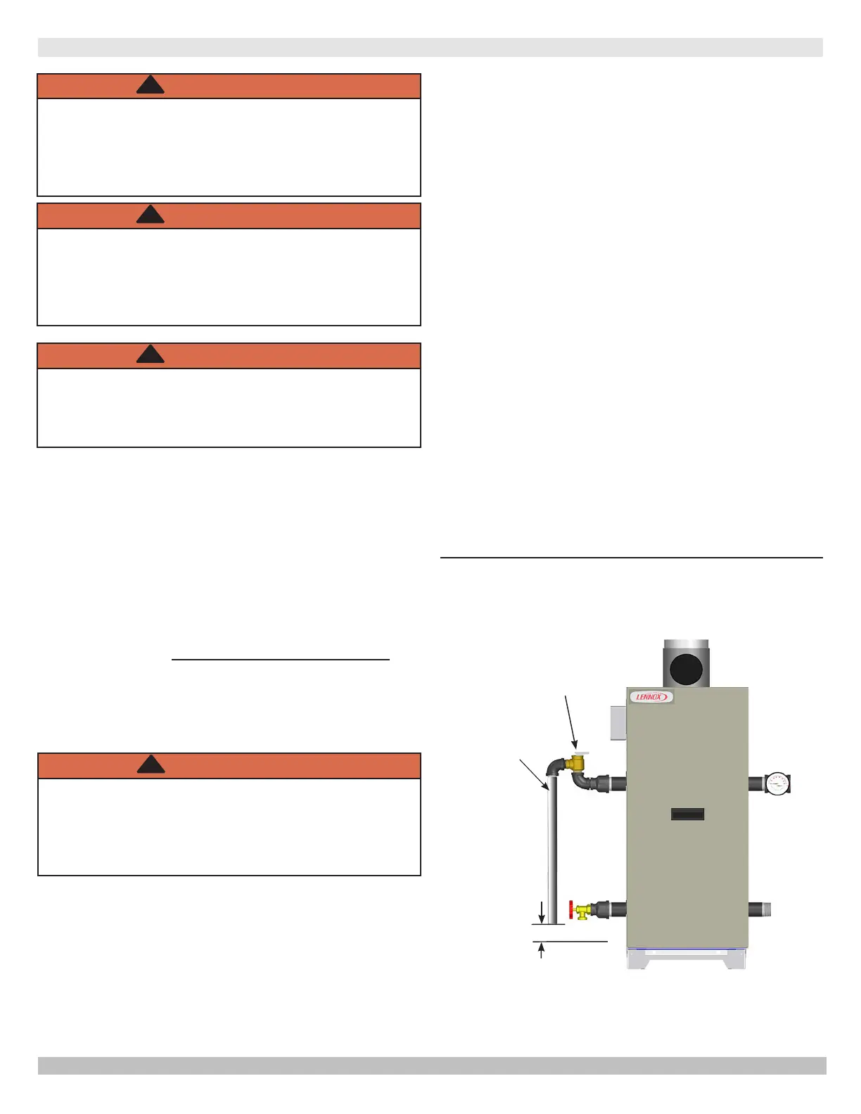
Figure 4-1 - Safety Relief Valve
WARNING
!
4 . 2 S a f e t y R e l i e f V a l v e I n s t a l l a t i o n
See Figure 4-1
4.1 Connection Locations
•
boiler with water.
•
boiler, as desired.
•
tapping, as desired.
• ASME relief valve may be located o unused
supply tapping IN UPRIGHT POSITION ONLY.
•
on near boiler piping using contractor supplied tees
with no valves.
WARNING
!
WARNING
these instructions could result in death or serious
!
Check local codes for maximum
distance from oor or allowable
safe point of discharge.
RELIEF VALVE
DISCHARGE
LINE
WARNING
installed with spindle in upright position only,
!
B.
discharge line;
C.
D.
E.
discharge line;
F.
G. be as short and straight as possible;
PN 240012889 Rev. A [07/31/2020]
 Loading...