Page 38
F2F1
Option 1 − System Troubleshooting − Harmony
®
II Zone Control with
G32V/G21V/GSR21V and Condensing Unit
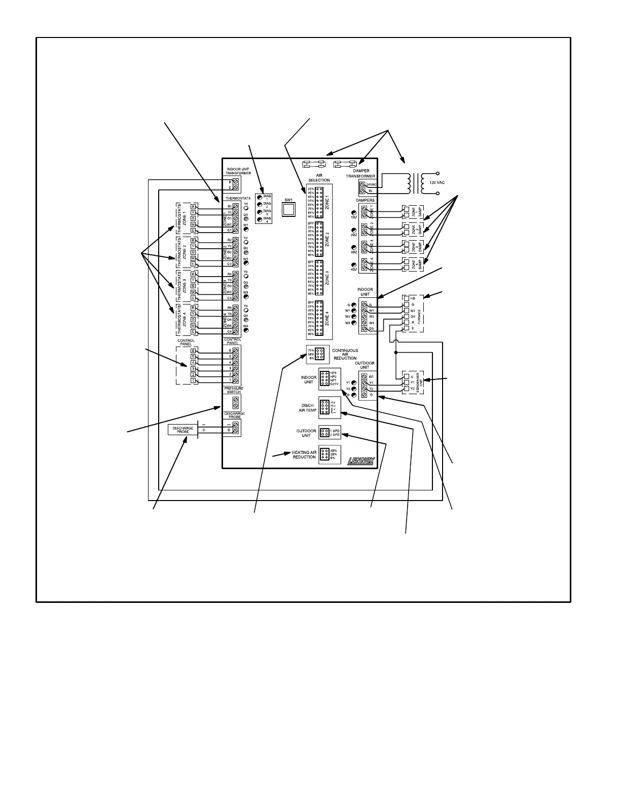
Figure 29
Line Voltage to transformer?
24VAC from transformer to control center?
Fuses OK?
Are all wire connections good? Are all wire
connections correct?
Error code present? If so,
see diagnostic section of
this manual.
Are LEDs on panel lit? Check
wiring?
Does panel readily switch be-
tween Zone, Central and Off?
Does panel readily switch be-
tween Cool, Heat and Auto?
Does panel readily switch be-
tween Fan On and Auto?
Are wires run adjacent to AC
line voltage wires?
Is wiring correct and in
good condition?
Do dampers respond to de-
mand? 0 volts AC = open.
24 volts AC = closed.
Dampers should drive
closed when 24 volts is
jumpered to damper motor.
Are jumpers set correctly?
Only one jumper is allowed
per zone.
Switch should not be installed.
Heat/cool thermostat used?
(Must not use heat pump
thermostat.)
If electronic thermostat is
used, does it have relay
switching output? If not, isola-
tion relays may need to be
used.
24VAC supplied to each ther-
mostat terminal R from con-
trol center?
Check each thermostat for
output signal when calling.
Heating output?
Cooling output?
Blower output not used, no
need to check.
Are anticipators working and
set correctly?
Is discharge probe installed?
Probe should be located in dis-
charge air plenum before first
bend or branch. Is probe in cor-
rect location?
Is it wired correctly?
After 5 minutes heating operation,
is discharge air between 95F
and 125F?
After 5 minutes cooling operation,
is discharge air between 53F
and 70F?
Is jumper set correctly?
Does jumper provide appropri-
ate speed reduction? If no,
check indoor unit before replac-
ing control center.
Is jumper set correctly?
One jumper may be used.
If one jumper is used, it must be on
a C terminal. Jumper placed on an
H terminal has no effect.
Is jumper set correctly for
G32V/G21V/GSR21V?
Are appropriate outputs
energized in response
to demand?
Are thermostats wired correctly?
Does control center respond appro-
priately to demand?
This troubleshooting diagram lists common trouble spots. Rather than providing solutions, this diagram asks questions about the hookup
and operation of system equipment. Good troubleshooting skills and information provided elsewhere in this manual are necessary.
Does control center energize
appropriate outputs? During
Cooling? During Heating?
24VAC from furnace trans-
former to R?
Does furnace respond to out-
puts?
Does blower speed change as
zone demand changes? If no,
does DS output vary from 0 to
25VDC?
Does outdoor unit re-
spond to demand?
Is it operating properly?
DAMPER TRANSFORMER
or GAS
 Loading...