13
1.10.9. SystemConguration/E-HeatStages)
TheSYSTEMcongurationjumpersmustbeinsertedtoselectthetypeofcooling
andheatingsystemthathasbeeninstalledandtheE-HEATStagesjumperdenes
ifthesystemisdualfuelordenesthenumberofelectricheatingstagesused.
1.10.9.1. Gas Furnace and Air Conditioning
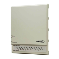
For a gas furnace and air conditioning
combinations, put the jumper on
GAS (as shown) and select the
number of equipment cooling stages
by placing the cooling jumper to the
appropriate site (place on 1COOL for
1stage cooling or 2COOL for 2-stage
cooling).
SYSTEM
Configuration
HP
2COOL
2HP
GAS
1COOL
1HP
E-HEAT
Stages
DF
1
2
3
IN A/C AND GAS FURNACE
CONFIGURATION, “HP”
AND “E-HEAT” JUMPERS
ARE IGNORED
Inthisconguration,themaximumdischargetemperature(uppertemperaturelimit)
atwhichthefurnaceisallowedtorunis160°F(exceptwhen140FDASjumperisin
place). At the upper limit, the zone control system removes any heat demand from
thefurnaceforaminimumofveminutesanduntilthetemperaturecomesback
within normal operating temperatures.
While at or above the upper temperature limit, the control unit signals for continuous
blower operation to those zones from which a thermostat heat demand is received.
When setting up the furnace control board options, be sure to set the BLOWER-
OFF DELAY to no greater than 210 seconds.
1.10.9.2. HeatPumpwithElectricBackupHeat
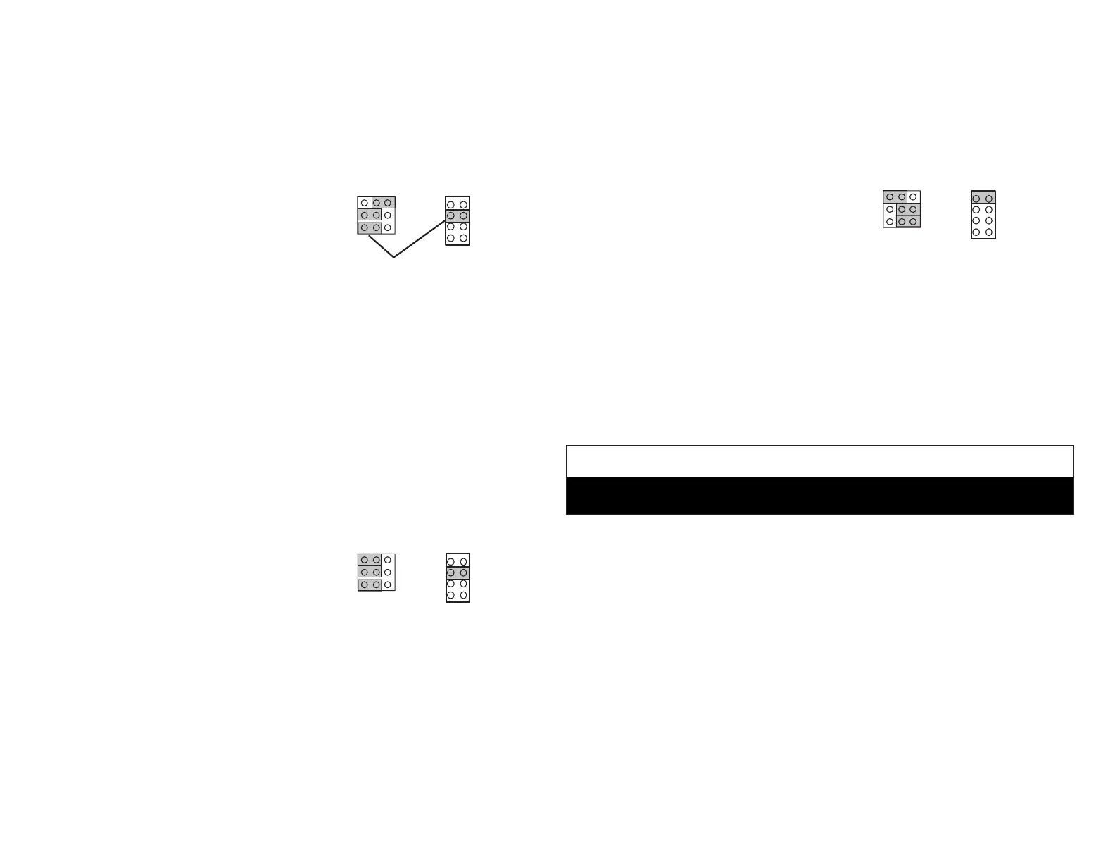
For heat pump with electric backup
heat, select HP position as shown in
this diagram.
SYSTEM
Configuration
HP
2COOL
2HP
GAS
1COOL
1HP
E-HEAT
Stages
DF
1
2
3
Inthisconguration,themaximumdischargetemperaturetheelectricheatorheat
pump is allowed to run is 135°F.At that temperature, the zone control system
removesdemandfromtheheatingunitforaminimumofveminutesanduntilthe
temperature returns to the normal operating temperature range. While at or above
135°F,thecontrolunitsignalsforcontinuousbloweroperationtothosezonesfrom
which a thermostat heat demand is received.
Select the number of equipment cooling stages by placing the COOL stages jumper
to the appropriate side (1COOL or 2COOL). Similarly, set the number of Heat Pump
stages (1HP or 2HP). Jumper settings on the above diagram illustrate the proper
settings for a two stage heat pump and two-stage air conditioning system.
When using a heat pump with electric backup heat, insert an E-HEAT jumper to
select the total number of available electric heat stages. The diagram above shows
asingleheat-stripconguration.
1.10.9.3. Heat Pump - Dual Fuel heating, 1-stage or 2 Stage Heat Pump and
Gas Furnace
This diagram shows a dual-fuel
conguration (heat pump for heat
and cool with gas backup heat).
SYSTEM
Configuration
HP
2COOL
2HP
GAS
1COOL
1HP
E-HEAT
Stages
DF
1
2
3
HP position must be jumpered for Dual Fuel applications and the E-Heat Stages
jumper must be set to “DF” for dual fuel operation.
Select the number of equipment cooling stages by placing the COOL stages
jumper to the appropriate side (1COOL or 2COOL). Similarly, set the number of
Heat Pump stages (1HP or 2HP). Jumper settings on the above diagram illustrate
the proper settings for a one stage heat pump and one stage of cooling.
1.11. Common System Component Wiring
Use thermostat wire to connect dampers, damper transformers, and the DAS
probe with the zone control system.
IMPORTANT
Avoid running any control wiring close to AC house wiring. If this cannot be
avoided, limit close parallel of power and control wiring to a few feet.
1.11.1. Dampers and Damper Transformer
Connect dampers to the zone control panel. A total of six dampers may be
connected at the damper output terminals on the zone control panel. If additional
dampers are used, additional transformers and relays will be needed.
Fuse F1 will protect the damper outputs from a short circuit or overload in the
damper wiring.
If dampers are applied to the return duct system, the dampers for each zone must
be wired in parallel. Connect damper transformer to zone control panel terminal
block.
 Loading...


