30
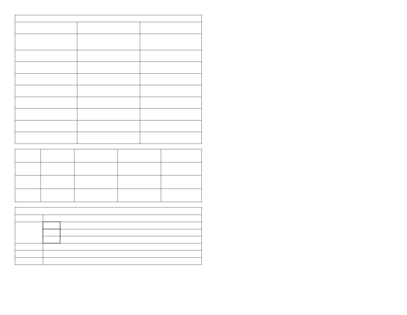
Panel Setup:
9 Heating staging jumper Circle one: 85 90 100 110
120 130
Recommended 120 deg-F
9 Zone 1 PIAB 140F DAS
jumper in place
Circle one: Yes No See “1.10.4. Zone 1 PIAB
Jumpers – 140ºF DAS” on
page 10.
9 Cooling staging jumper Circle one: 50 55 60 Select desired discharge air
temp during cooling
9 Cont. Air Reduction jumper Circle one: 0 25 50 75 Percentageairowreduction
for continuous fan operation
9 Heating Air Reduction
jumper
Circle one: 0 20 40 Percentageairowreduction
for heating mode
9 SystemConguration
jumpers
Circle one: HP GAS Set to GAS
9 Stages Circle one: 2COOL 1COOL Set to match condenser, 1 or
2 stage
9 Stages Circle one: 2HP 1HP Ignored for gas heat, non-heat
pump application
9 E-HEAT Stages Circle one: DF 1 2 3 Ignored for gas heat, non-heat
pump application
9 Desired total system CFM
with all zones calling:
Total system CFM per tables: Minimum CFM:
9 Zone 1 Name: Desired CFM: PIAB Setting: Actual CFM:
9 Zone 2 Name: Desired CFM: PIAB Setting: Actual CFM:
9 Zone 3 Name: Desired CFM: PIAB Setting: Actual CFM:
9 Zone 4 Name: Desired CFM: PIAB Setting: Actual CFM:
Field Wiring Checklist
√ Indoor Unit Wiring Completed:
DS” on Harmony III to “DS” on indoor unit connected
”C” on indoor unit connected to Harmony III transformer “C”,
No connection to “Y1” or “Y2” on indoor unit.
√ Outdoor Unit Wiring Completed
√ Thermostat and Damper Wiring Completed
√ Discharge Sensor wired to Harmony III zoning system
3.3.4. Zone Control Operation in a Gas Furnace System
This section describes the operation of the zone control in a system that uses a
gas furnace.
3.3.4.1. Zone Thermostats
Only electronic thermostats with a C terminal may be used with the zone control
system. The zone control system distinguishes between heat pump and heat/cool
applications via the SYSTEM jumper placement on the zone control panel.
1. Cool / Heat / Auto-Changeover Modes — Zone thermostats send a heating
or cooling signal to the zone control panel. Thermostat servicing zone 1 is the
central control thermostat. Zones 2, 3 and 4 each have their own thermostat.
Thermostats may be standard or auto-changeover type.
Heat and cool demands present at the same time from different zones (opposing
demands)aresatisedonarstcomerstservedbasis.Ifaheatingdemand
and a cooling demand reach the zone control panel at the same time, the
heatingdemandissatisedrst.Ifopposingdemandspersist,thesystemwill
work to satisfy the current demand for a maximum of 20 minutes, then switch
over and try to satisfy the opposing demand for a maximum of 20 minutes.
Wheneitherdemandissatised,thesystemworkstosatisfytheotherdemand.
NOTE: Allowing opposing demands to persist may consume excess energy. If this
condition continues, check the installation (i.e. zone arrangement, supply
registers, return registers, zone loads etc.) and make adjustments as
necessary. “Table 14. Time Delays” on page 60 shows the time delays
that may be expected when opposing demands are received from the
zone thermostats.
The zone control system acknowledges a new or opposing demand as soon
asitisreceivedbyilluminatingthatzone’sthermostatinputlights.Iftherst
demandisnotsatisedbythetimethedelayselapse,thesystemswitches
over and begins satisfying the opposing demand. During the switch-over, a
delay may be imposed before the system begins satisfying the new demand.
2. Fan On / Auto Mode — Zone thermostats can send a continuous fan signal
to the zone control system. The zone control system will signal the blower
to supply air to zones calling for continuous fan while no other conditioning
calls exist. When the zone control system receives a conditioning call while
satisfying a demand for continuous fan, it signals the damper controlling the
continuous-fanzonetoclose.Aftertheconditioningdemandissatised,the
continuous-fan zone damper is signaled to reopen.
3.3.4.2. Balance Point Setting
(Dual Fuel Systems) Balance Point Sensor (kit 10Z23) communicates with the
zone control panel whether or not to force the Gas Furnace to satisfy heating
demands, based on a comparison of the Balance Point setting with the outdoor
temperature. Terminals 2-3 close on temperature fall to lock out heat pump.
 Loading...


