24
2.4. Heat Pump System Start-Up and Checkout
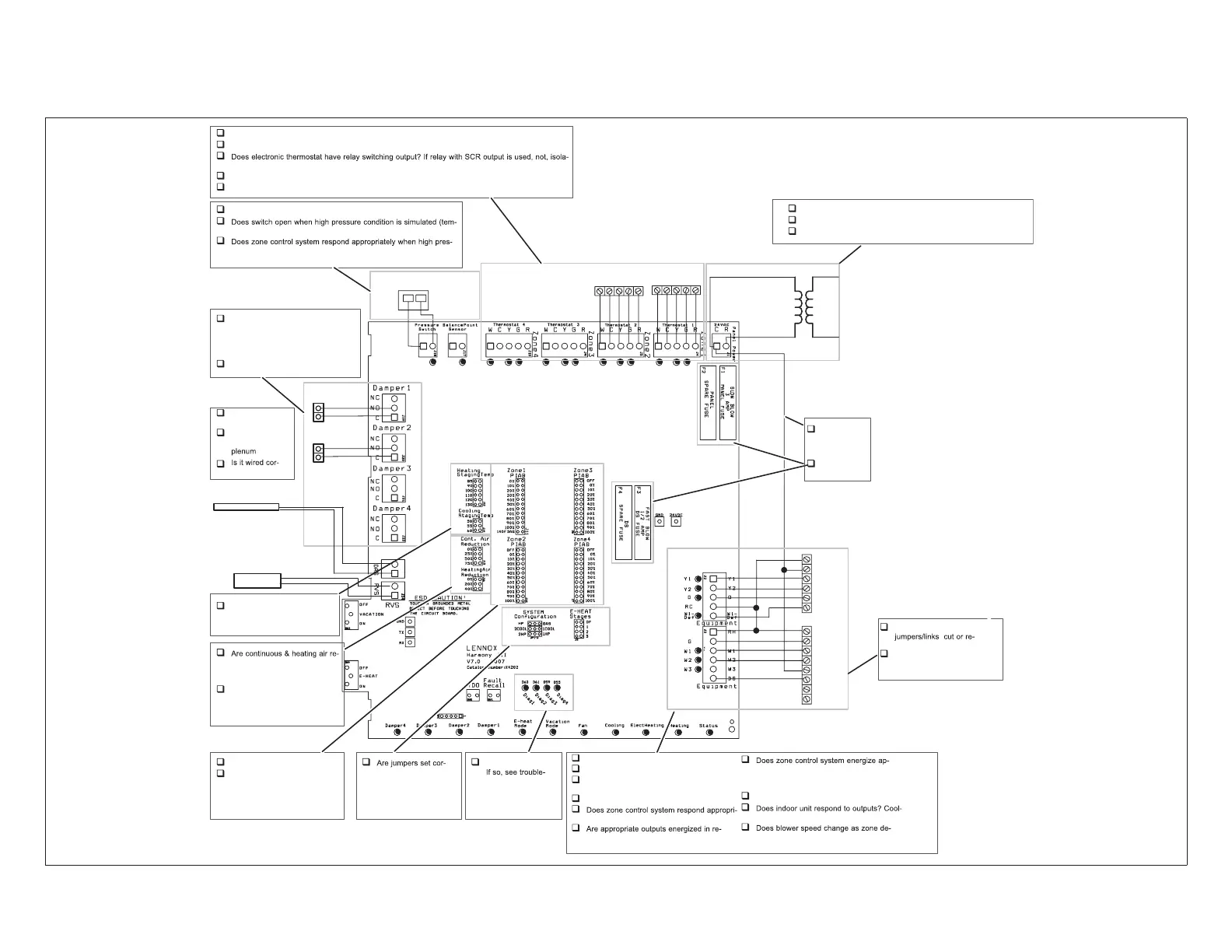
2.4.1. Troubleshooting Diagram
Do dampers respond to demand? 0
volts AC = open. 24 volts AC =
closed. Dampers should drive closed
when 24 volts is jumpered to damper
motor.
Is wiring correct & in good condition?
Are thermostats wired correctly?
Does zone control system respond appropriately to demand?
tion relays may need to be used.
24VAC supplied to each thermostat terminal R from zone control system?
Check each thermostat for output signal when calling. Heating output W1? Cooling output Y1?
Error code present?
shooting/diagnostic
section of this
manual .
rectly for auxiliary
heat and cooling?
Is discharge
probe installed?
Is probe located
in discharge air
rectly?
Does outdoor unit respond to demand?
Is it operating properly?
Test Defrost. Does outdoor unit initiate and
terminate defrost correctly?
W1 energized during defrost?
ately during defrost?
sponse to demand?
propriate outputs? During Cooling? During
Heating? During Defrost? During Emer.
Heating?
24VAC from furnace transformer to R?
ing? Heating? Defrost? Emer. Heating?
mand changes? If no, does DS output vary
from 0 to 25VDC?
Line Voltage to transformer?
24VAC from transformer to zone control panel?
Are all wire connections good? Are all wire connections correct?
Pressure Switch installed in correct position?
porarily blocking airflow in heating mode)?
sure condition is simulated (temporarily disconnecting switch
simulates high pressure).
DAMPERS
240
VAC
24
VAC
Thermostat 2Thermostat 1
W C Y G R
DISCHARGE
AIR SENSOR
THERMOSTATS
Are PIAB jumpers set correctly?
Only 1 jumper per Zone? (Zone
Control System Jumper Settings
duction jumpers set correctly?
On heat pumps, Heating Air
Reduction must be 0%.
Do jumpers provide appropriate
speed reduction? If no, check
indoor unit before replacing
zone control panel.
Have heating and cooling
staging jumpers been set for
desired 2nd stage operation?
PRESSURE
SWITCH
R
C
Y1
Y2
O
W1
R
G
W1
W2
C
DS
Y1
Y2
HEAT PUMP
VARIABLE
SPEED AIR
HANDLER
W C Y G R
HUMIDITROL ZONING
ACCESSORY CONTROL
Verify Air Handler
moved
Verify NO connections
made to Y1 or Y2.
“C” connected
to “C”?
Fuses OK?
ZONE PANEL TRANSFORMER
TO AIR HANDLER
POWER SUPPLY
Figure 21. Option 2 - Typical Lennox Heat Pump and Lennox Variable-Speed Air Handler (Troubleshooting)
 Loading...


