19
2.1.6. Defrost Tempering Kit
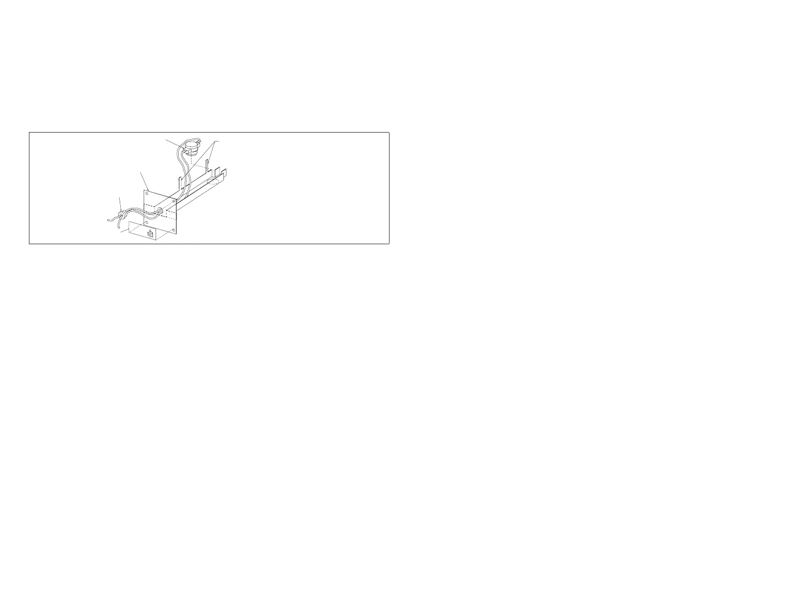
A defrost tempering kit (67M41) may be implemented in a dual-fuel (Option 3)
system. This kit consists of a thermostat probe/switch which is installed between
thefurnaceandthe evaporator coiltoturnthefurnace on (at 80°F)andoff(at
90°F) during a defrost cycle. This tempers the discharge air and protects the
compressorfromhighrefrigerationpressuresduringdefrost.Thefollowinggure
show the defrost temperating kit components and see “Figure 4. Discharge Air
Sensor Installation” on page 8 for location of the probe.
LIMIT CONTROL
MOUNTING
BRACKET
STRAIN
RELIEF
LABEL
WHEN FULLY ASSEMBLED,
TABS ARE BENT DOWN TO
HOLD CONTROL AND WIRES
IN PLACE.
Figure 19. Defrost Tempering Limit Control
 Loading...


