Page 8
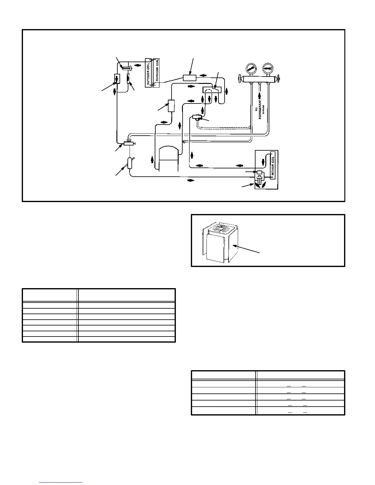
STRAINER
FILTER DRIER
WITH INTERNAL
CHECK VALVE
DISCHARGE
MUFFLER
COMPRESSOR
VAPOR LINE
VALVE
REVERSING
VALVE
INDOOR
UNIT
LIQUID
LINE
VALVE
THERMOMETER
WELL
EXPANSION
VALVE
SUCTION
HIGH
PRESSURE
HP25 COOLING CYCLE
(Showing Gauge Manifold Connections)
FIGURE 7
NOTE-Use gauge ports on vapor line valve and liquid valve for evacuating refrigerant lines
and indoor coil. Use suction gauge port to measure suction pressure during charging.
EXPANSION
VALVE
CHECK
VALVE
CHARGE COMPENSATOR
5- If outdoor temperature is 60F (15C) or above,
place thermometer in well and read liquid line
temperature. Difference between ambient and liq
uid line temperatures should match values given
in table 4. Refrigerant must be added to lower ap
proach temperature. Remove refrigerant from sys
tem to increase approach temperature.
TABLE 4
Model
Liquid Temp. Minus
Ambient Temp. F (C)
HP25-211
HP25-311
HP25-410
HP25-460
8 (4)
8 (4)
9 (5)
9 (5)
Approach Method-Expansion Valve Systems
HP25-261 8 (4)
HP25-510
HP25-650
5 (3)
5 (3)
6- If ambient temperature is less than 60F (15C), air
flow might need to be restricted to achieve pressur
es in the 200-250 psig (1379-1724 kPa) range (See
figure 8). These higher pressures are necessary for
checking charge. Block equal sections of air intake
panels, moving obstructions sideways as shown
until liquid pressure is in the 200-250 psig
(1379-1724 kPa) range.
BLOCKING OUTDOOR COIL
FIGURE 8
OUTDOOR COIL SHOULD BE BLOCKED
ONE SIDE AT A TIME WITH CARDBOARD
OR PLASTIC SHEET UNTIL PROPER TEST
ING PRESSURES ARE REACHED.
CARDBOARD OR PLASTIC SHEET
7- Read liquid line temperature. Read liquid line pres
sure from gauge and convert to condensing tem
perature using standard R-22 temperature/pres
sure conversion chart. The difference between the
liquid line temperature and the conversion temper
ature is the subcooling temperature (subcooling =
conversion temperature minus liquid tempera
ture). Subcooling should approximate values given
in table 5. Add refrigerant to increase subcooling
and remove refrigerant to reduce subcooling.
TABLE 5
Subcooling Method-Expansion Valve Systems
Model Subcooling F (C)
HP25-261/311/410
HP25-460
3 +
2 (2 + 1)
8 +
2 (4 + 1)
HP25-211 8 + 2 (4 + 1)
HP25-510
HP25-650
10 +
2 (6 + 1)
12 +
2 (7 + 1)

 Loading...