Page 9
Compressor Oil Charge
Table 6 gives compressor oil charge for HP25 units. Re
fer to Lennox Cooling Service Handbook for correct pro
cedure for checking and adding compressor oil.
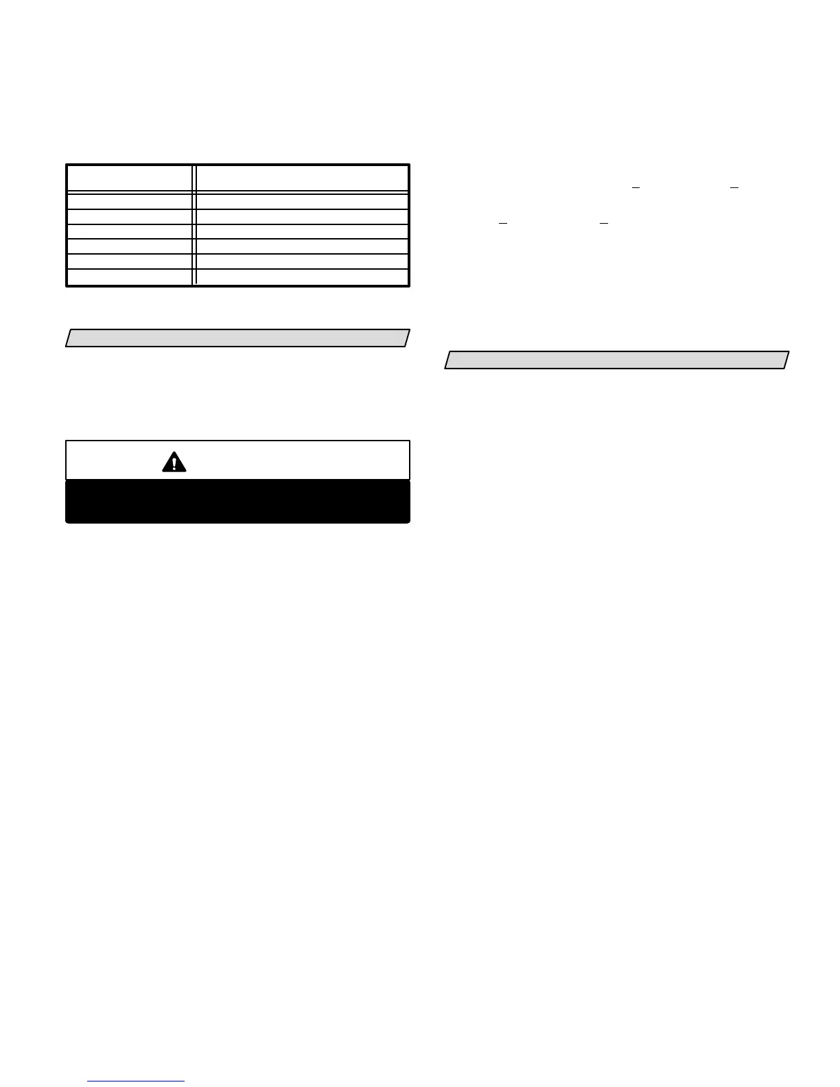
COMPRESSOR OIL CHARGE
TABLE 6
UNIT MODEL NO.
COMPRESSOR OIL CHARGE
ounces (liters)
HP25-211
HP25-410
HP25-460 38 oz.* (1.12 L)
*Shipped with conventional white oil (Sontex 200LT). 3GS oil may be
used if additional oil is required.
34 oz.* (1.01 L)
HP25-261 & -311 28 oz.* (0.83 L)
HP25-510 52 oz.* (1.54 L)
HP25-650 54 oz.* (1.60 L)
24 oz.* (0.71 L)
SYSTEM OPERATION
Discharge Thermostat
The scroll compressor is equipped with a discharge
thermostat which prevents the occurrence of danger
ously high discharge temperatures. This thermostat
cuts in at 130F (54C) and cuts out at 280F (138C) .
CAUTION
Danger of Equipment Damage.
Do not bypass the discharge thermostat.
Filter Drier
The drier is equipped with an internal check valve for
correct refrigerant flow (Refer to figure 7). If replace
ment is necessary, order another of like design and ca
pacity. A liquid line strainer gives additional compressor
protection.
Thermostat Operation
Some heat pump thermostats incorporate isolating
contacts and an emergency heat function (which in
cludes an amber indicating light). The thermostat is
not included with the unit and must be purchased
separately.
Emergency Heat (Amber Light)
An emergency heat function is designed into some ther
mostats. This feature is applicable only to those systems
with auxiliary electric heat staged by outdoor thermo
stats. When the thermostat is placed in the emergency
heat position, the outdoor unit control circuit is isolated
from power and field-provided relays by-pass the out
door thermostats. An amber indicating light simulta
neously comes on to remind the homeowner that the
unit is operating in the emergency heat mode.
Emergency heat is usually used during a heat pump
shutdown.
Compressor Timed-Off Control
This unit is equipped with a time delay which protects
the compressor by preventing short-cycling.
High Pressure Switch
The HP25 is equipped with an auto-reset high pressure
switch (single-pole, single-throw) which is located on
the liquid line. The switch shuts off the compressor
when discharge pressure rises above the factory set
ting. The switch is normally closed and is permanently
adjusted to trip (open) at 410 +
10 psig (2827 + 69 kPa).
The switch resets (closes) when the pressure drops be
low 210 +
20 psig ( 1448+138 kPa).
Crankcase Heater
HP25-413 & -463-1Y three-phase units only are
equipped with a crankcase heater which must be ener
gized for 24 hours before attempting to start compres
sor. To prevent compressor operation, set thermostat
so there is no demand. Apply power to unit.
DEFROST SYSTEM
The defrost system includes two components: a de
frost thermostat, and a defrost control.
Defrost Thermostat
The defrost thermostat is mounted on the liquid line be
tween the check/expansion valve and the distributor.
When defrost thermostat senses 35F (2C) or cooler, its
contacts close and send a signal to the defrost control
board to start the defrost timing. It also terminates de
frost when the liquid line warms up to 70F (21C).
Defrost Control
The defrost control board has the combined func
tions of a time/temperature defrost control, defrost
relay, time delay, diagnostic LEDs and field connec
tion terminal strip.
The control provides automatic switching from normal
heating operation to defrost mode and back. During
compressor cycle (call for defrost), the control accumu
lates compressor run times at 30, 60 or 90 minute field
adjustable intervals. If the defrost thermostat remains
closed when the accumulated compressor run time
ends, the defrost relay is energized and defrost begins.
Defrost Control Timing Pins
Each timing pin selection provides a different accu
mulated compressor run period during one thermo
stat run cycle. This time period must occur before a
defrost cycle is initiated. The defrost interval can be
adjusted to 30, 60 or 90 minutes. See figure 9. The de
frost period is a maximum of 14 minutes and cannot
be adjusted. If no timing is selected, the control de
faults to 90 minutes.
A TEST option is provided for troubleshooting. When
the jumper is placed across the TEST pins, the timing of
all functions is reduced by a factor of 128. For example,
a 90 minute interval during TEST is 42 seconds and the
14 minute defrost is reduced to 6.5 seconds.
 Loading...
