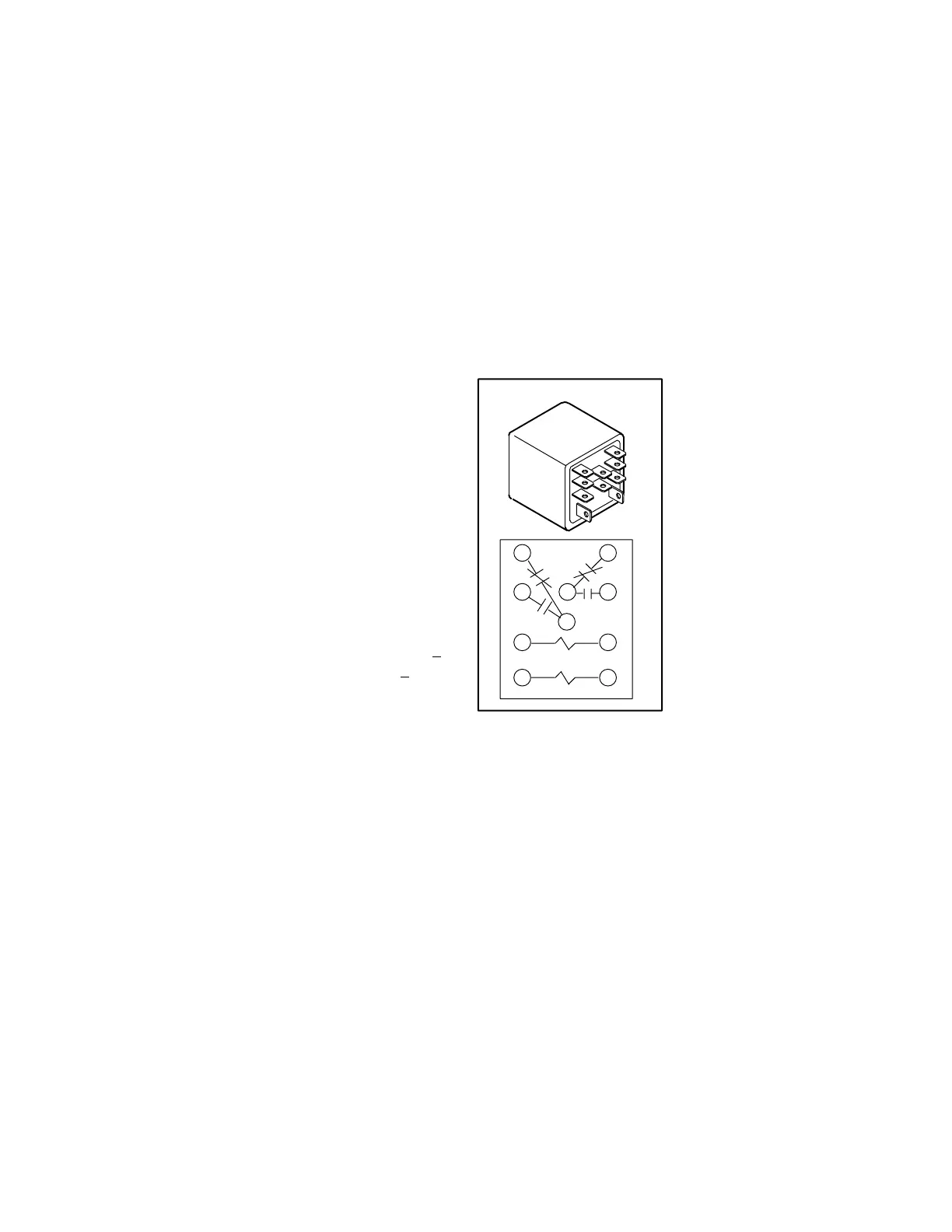
LATCH RELAY K6
14
568
9
10
12
13 14
FIGURE 5
SET
RESET
Page 6
I−UNIT COMPONENTS
The HP29−090 and HP29−120 components are shown in
figures 1 and 2.
A−CONTROL BOX COMPONENTS
The HP29−090 control box components are shown in fig
ure 3. The HP29−120P control box components are shown
in figure 4.
1 − Disconnect Switch S48
(Option −2 Units)
HP29 heat pumps units may be equipped with an optional
disconnect switch S48. S48 is a factory−installed toggle
switch used to disconnect power to the unit.
2 − Outdoor Fan Capacitors C1 (all units)
and C2 (120P)
All HP29 units use single−phase condenser fan motors.
Motors are equipped with a fan run capacitor to maximize
motor efficiency. Outdoor fan capacitors C1 and C2 assist
in the start up of condenser fan motors B4 and B5. Capaci
tor ratings are on outdoor fan motor nameplates.
3 − Compressor Contactor K1 (all units)
All compressor contactors are three−pole−double break
contactors with a 24V coil. K1 energizes compressor B1 in
both HP29−090 and HP29−120 units. The contactor is en
ergized from indoor thermostat terminal Y when thermo
stat demand is present.
4 − Low Ambient Thermostat S41
(HP29−120 only)
S41 is a N.C. limit which opens on temperature fall at 55+
5_F. The switch resets when temperature rises to 65+ 6_F.
S41 opens and de−energizes K68 which de−energizes out
door fan B5. When S41 closes, fans will be re−energi
zed.This intermittent fan operation increases indoor evap
orator coil temperature to prevent icing.
5 − Latch Relay K6 (all units)
HP29 units are plumbed so that the unit is in cooling mode
when the reversing valve is energized. Latch relay K6 con
trols operation of the reversing valve and is controlled (indi
rectly) by the indoor thermostat. The combined operation
of latch relay K6 and transfer relay K8 allows the HP29
heat pumps to use a conventional heat/cool thermo
stat instead of a heat pump thermostat.
A latch relay (figure 5 ) has two coils: a SET" coil and a
RESET" coil. When 24VAC is applied to the SET" coil, the
normally open contacts close and the normally closed con
tacts open. When power is removed from the SET" coil,
nothing happens; the NO. contacts remain closed and the
N.C. contacts remain open. The contacts do not return to
their normal position until the RESET" coil is energized.
Once the contacts are reset, they remain in their normal
position when power is removed.
HP29 units use a DPDT
latch relay. Each set of nor
mally open contacts con
trols a reversing valve.
When the SET" coil is en
ergized, the normally open
contacts close to energize
the reversing valve (there
by placing the unit in the
cooling mode). When pow
er is removed from the
SET" coil (such as when
thermostat demand is satis
fied), the normally open
contacts remain closed, the
reversing valve remains en
ergized and the unit re
mains in the cooling mode.
When a heating demand is initiated, the RESET" coil is
energized. The normally open contacts open and the re
versing valve is deenergized (thereby placing the unit in
the heating mode). When heat demand is satisfied and
power to the RESET" coil is removed, the normally open
contacts remain open, the normally closed contacts re
main closed and the unit remains in the heating mode.
 Loading...
