EasyManuals Logo

Lennox KGC Series User Manual

Lennox KGC Series
56 pages
To Next Page IconTo Next Page
To Previous Page IconTo Previous Page
Page #14 background imageLoading...
Page #14 background image
Page 14
I-UNIT COMPONENTS
      

-


ELECTROSTATIC DISCHARGE (ESD)
Precautions and Procedures
CAUTION
   󰀨
electronic components. Take precautions
to neutralize electrostatic charge by
touching your hand and tools to metal
prior to handling the control.

        
The control box is located in the upper portion of the com-
pressor compartment.
1-Disconnect Switch S48
All units may be equipped with an optional disconnect
switch S48 or circuit breaker CB10. S48 and CB10 are
-
cian to disconnect power to the unit.
2-Control Transformer T1
All use a single line voltage to 24VAC transformer installed
in the control box. The transformer supplies power to con-
trol circuits in the unit. The transformer is rated at 70VA


-
age transformers use a single primary voltage tap.
BLUE YELLOW
ORANGE
RED
BLACK
230 VOLTS
208 VOLTS
PRIMARY
SECONDARY
208/230V TRANSFORMER
FIGURE 3
3-C. A. I. Transformers T3 575V Only

in the control box. The transformers have an output rating
        

4-Terminal Strip TB1
All indoor thermostat connections are made at terminal
        
-
         
place.
5-Condenser Fan Capacitors C1 & C2


of capacitor or outdoor fan motor nameplate.
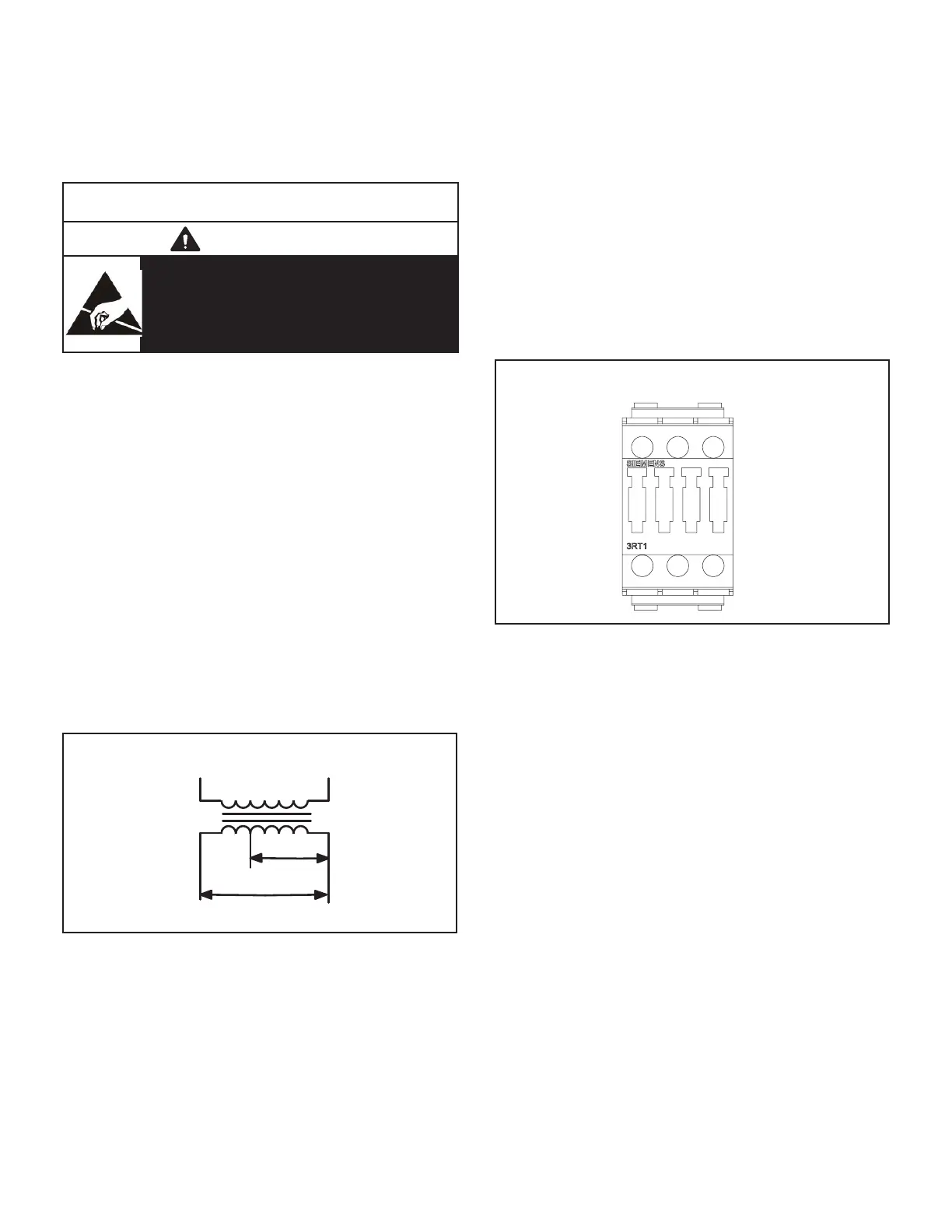
6-Compressor Contactor K1 & K2
All compressor contactors are three-pole-double-break
         
K2 energize compressors B1 and B2 in response to

CONTACTOR
FIGURE 4
7-Blower Contactor K3
-
ble- break contactor with a 24VAC coil used to energize
the indoor blower motor B3 in response to blower de-
mand. K3 is energized by a thermostat cooling demand.

8-Condenser Fan Relay K10
Outdoor fan relay K10 is a DPDT relay with a 24VAC coil.



          
-


fan B10 is energized.

Questions and Answers:

Question and Answer IconNeed help?

Do you have a question about the Lennox KGC Series and is the answer not in the manual?

Lennox KGC Series Specifications

General IconGeneral
BrandLennox
ModelKGC Series
CategoryAir Conditioner
LanguageEnglish

Related product manuals