EasyManuals Logo

Lennox KGC Series User Manual

Lennox KGC Series
56 pages
To Next Page IconTo Next Page
To Previous Page IconTo Previous Page
Page #37 background imageLoading...
Page #37 background image
Page 37
V- SYSTEMS SERVICE CHECKS
A-Heating System Service Checks
         

       
authorities having jurisdiction for local code requirements.
       
information.
1-Gas Piping
        

the unit. Supply gas pipe must not be smaller than the
       
details.
2-Testing Gas Piping
NOTE - In case emergency shutdown is required, turn o
the main manual shut-o valve and disconnect the main
power to the unit. These controls should be properly la-
beled by the installer.
    
disconnected and isolated. Gas valves can be damaged
if subjected to more than 0.5 psig [14”W.C. (3481 Pa)].
See FIGURE 22.

preferred means. Common kitchen detergents can cause
harmful corrosion on various metals used in gas piping.
The use of specialty Gas Leak Detector is strongly
recommended. It is available as part number 31B2001.

Do not use matches, candles, ame or any other
source of ignition to check for gas leaks.
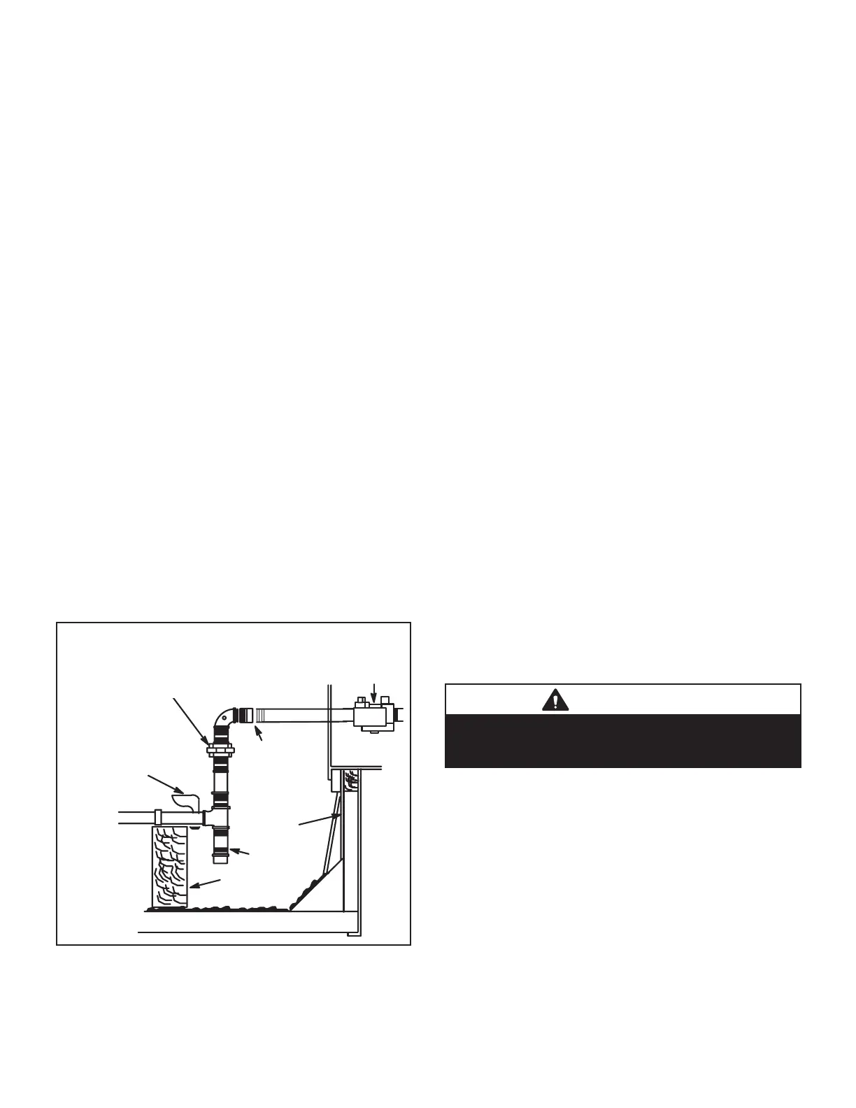
UNIT
GROUND
JOINT UNION
MANUAL MAIN
SHUT-OFF VALVE
(REFER TO LOCAL CODES)
GAS PIPING
SUPPORT
DRIP LEG
ROOF
MOUNTING
FRAME
GAS PIPING COMPONENTS
REFER TO INSTALLATION INSTRUCTIONS
VALVE
CAP HERE
TO ISOLATE
VALVE WHEN
PRESSURE
TESTING
LINE
FIGURE 22
3-Testing Gas Supply Pressure

the inlet pressure tap located on unit gas valve GV1. Test


range of the following values. Low pressure may result in




  

        


      
with the one closest to the supply gas main and progressing
to the one furthest from the main. Multiple units should
also be tested with and without the other units operating.
Supply pressure must fall within the range listed in the
previous paragraph.
4-Check and Adjust Manifold Pressure

manifold pressure. Move test gauge to the outlet pressure
          

The manifold pressure is factory set and should not require
adjustment. See TABLE 4. If manifold pressure is incorrect
and no other source of improper manifold pressure can be
         

adjustment screw.
All gas valves are factory-regulated. The gas valve should
󰀨
󰀨
󰀨
CAUTION
    󰀨   
󰀨
pressure to the manometer.
Manifold Adjustment Procedure
1 - Connect test gauge to the outlet pressure tap on the


state.
2 -         

and should not lift from the burner heads. Natural
gas should burn basically blue with some clear
streaks. L.P. gas should burn mostly blue with some
clear yellow streaks.
3 - 
record the manifold pressure and compare to the
values given in TABLE 4.

Questions and Answers:

Question and Answer IconNeed help?

Do you have a question about the Lennox KGC Series and is the answer not in the manual?

Lennox KGC Series Specifications

General IconGeneral
BrandLennox
ModelKGC Series
CategoryAir Conditioner
LanguageEnglish

Related product manuals