Page 39
VI-MAINTENANCE
WARNING
Electric shock hazard. Can cause injury
or death. Before attempting to perform
any service or maintenance, turn the
electrical power to unit OFF at disconnect
switch(es). Unit may have multiple power
supplies.
CAUTION
As with any mechanical equipment, contact with
sharp sheet metal edges can result in personal
injury. Take care while handling this equipment and
wear gloves and protective clothing.
A-Filters
should be checked and replaced when necessary with
NOTE - Filters must be U.L.C. certied or equivalent for
use in Canada.
PULL TO
REMOVE
FILTERS
FIGURE 23
B-Lubrication
All motors are lubricated at the factory. No further
lubrication is required.
C-Burners (Gas Units)
during the heating season. Before each heating season
examine the burners for any deposits or blockage which
may have occurred.
Clean burners as follows:
1 -
2 -
3 -
and lift the individual burners or the entire burner
as necessary.
4 - Locate the ignitor under the left burners. Check
ignitor spark gap with appropriately sized twist drills
Check the alignment of the ignitor and the sensor
6 - -
place access panel.
7 -
lighting instructions attached to unit and use inspec-
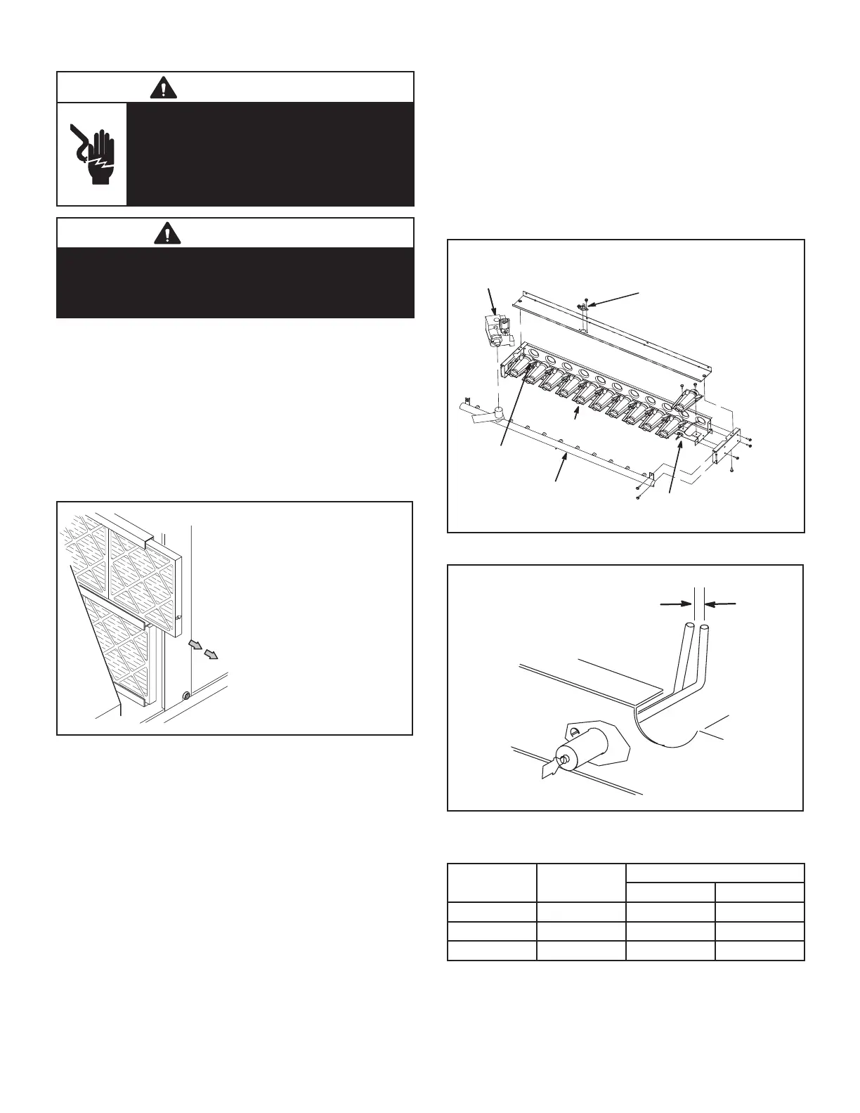
BURNER BOX ASSEMBLY
GAS MANIFOLD
FLAME
SENSOR
GAS
VALVE
(GV1), GV3)
BURNERS
FLAME
ROLLOUT
LIMIT
(S47), (S69)
SPARK
ELECTRODE
FIGURE 24
SPARK GAP
SHOULD BE 1/8”
(3mm)
FIGURE 25
TABLE 20
Dimension
Unit
Btuh Input
Length - in. (mm)
Ignitor Sensor
A 130K
B 180K
C 240K

 Loading...