Page 40
A
B
C
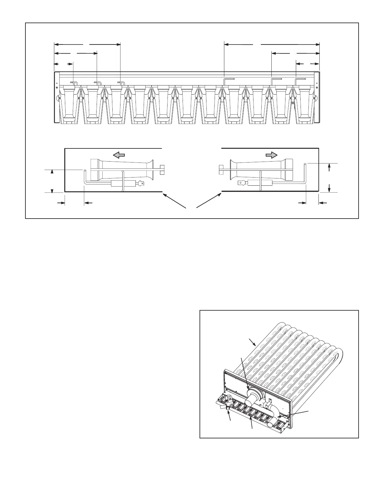
IGNITOR AND SENSOR POSITION
TOP VIEW
ROSNES WEIV EDISROTINGI WEIV EDIS
1-3/4”
(45mm)
3/8”
(10mm)
1-3/8”
(35mm)
BURNER BOX
Gas Flow Gas Flow
13/16”
(21mm)
A
B
C
ROSNESROTINGI
FIGURE 26
D-Combustion Air Inducer
A combustion air proving switch checks combustion
air inducer operation before allowing power to the gas
controller.
Gas controller will not operate if inducer is obstructed.
air inducer wheel should be checked and cleaned prior
periodically during the heating season to establish an
the condition of the inducer wheel can be determined by
looking through the vent opening.
Clean combustion air inducer as follows:
1 -
2 - Disconnect pressure switch air tubing from
combustion air inducer port.
3 -
screws from bracket supporting vent connector.
4 - Clean inducer wheel blades with a small brush and
connector to original location and secure with
retained screws.
6 - It is recommended that the combustion air inducer
gasket be replaced during reassembly.
HEAT EXCHANGER ASSEMBLY
BURNER
COMBUSTION
AIR INDUCER
VENT
CONNECTOR
GAS VALVE
HEAT
EXCHANGER
TUBE
FIGURE 27

 Loading...