-20
-29
-10
-23
0
-18
10
-12
20
-7
30
-1
40
4
50
10
60
16
70
21
80
27
90
32
100
38
0
10
30
40
50
60
70
80
90
100
20
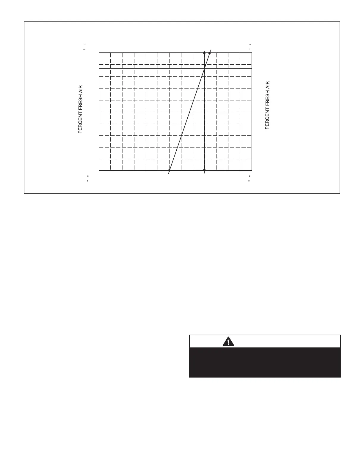
OUTDOOR AIR TEMPERATURE
0
10
30
40
50
60
70
80
90
100
20
MIXED AND RETURN AIR TEMPERATURE
CHART 1
CALCULATE MINIMUM FRESH AIR PERCENTAGE
A
BC
F
C
F
C
-20
-29
-10
-23
0
-18
10
-12
20
-7
30
-1
40
4
50
10
60
16
70
21
80
27
90
32
100
38
F
C
F
C
FIGURE 34
installed. The DCV SET potentiometer is factory-set at
Adjust the DCV SET potentiometer to the approximate
Dampers will open approximately halfway when CO2 rises
above setpoint. Adjust the DCV MAX potentiometer to the
NOTE - DCV Max must be set higher than economizer
minimum position setting for proper demand control ven-
tilation.
Economizer Operation
The occupied time period is determined by the thermostat
or energy management system.
Outdoor Air Not Suitable:
During the unoccupied time period dampers are closed.
During the occupied time period a cooling demand will
open dampers to minimum position and mechanical
cooling functions normally. See TABLE 24.
During the occupied time period dampers will open to DCV
Outdoor Air Suitable:
See TABLE 23 for economizer operation with a standard
twostage thermostat.
MAX may override damper free cooling position when
occupancy is high and outdoor air temperatures are low.
dampers will move to minimum position until discharge air
IMPORTANT
Remove jumper R and OC when unit is controlled
with a thermostat that has a night setback mode. If
reheat operation is desired during tjhis time, wire
A20 to R.

 Loading...