Page 10
TABLE 2
INVERTER UP-SIZING
Factory-Installed Inverter HP Replacement Inverter HP
2 5
3 7-1/2
5 10
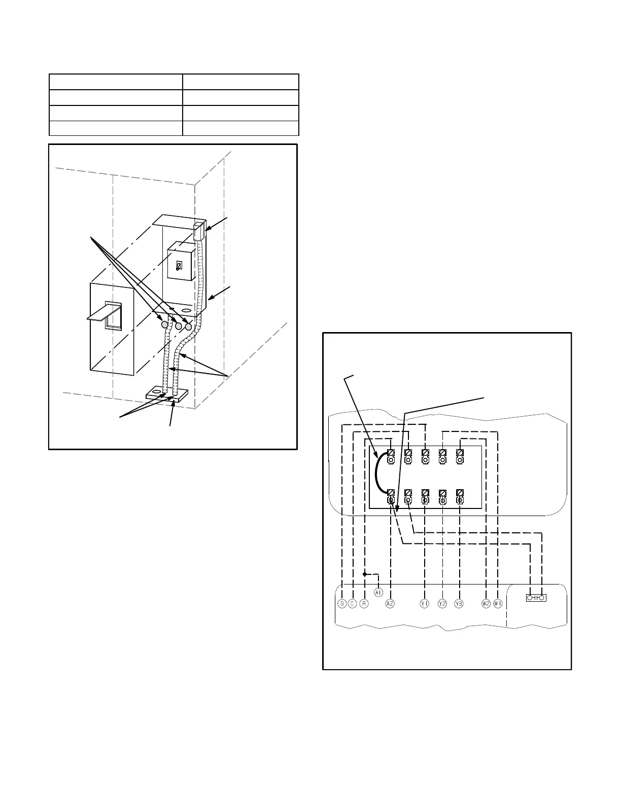
FIGURE 12
FIELD WIRING
SEAL
WATERTIGHT
RUN FIELD WIRING
IN FIELD PRO
VIDED CONDUIT
SIDE ENTRY
KNOCKOUTS
BOTTOM POWER
ENTRY
OPTIONAL
115V GFI
MAKE-UP
BOX
CONTROL WIRING
A-Thermostat Location
Room thermostat mounts vertically on a standard 2” X 4”
handy box or on any non-conductive flat surface.
Locate thermostat approximately 5 feet (1524mm)
above the floor in an area with good air circulation at
average temperature. Avoid locating the room
thermostat where it might be affected by:
-drafts or dead spots behind doors and in corners
-hot or cold air from ducts
-radiant heat from sun or appliances
-concealed pipes and chimneys
B-Control Wiring
NOTE - Units operate with 3 stages of cooling and require
a 3-stage thermostat. If a 3-stage thermostat is not
available, a 2-stage thermostat can be paired with a
field-installed Stage-Up Timer Kit to achieve desired
results. See Stage-Up Timer Kit installation instructions
for wiring.
1- Route thermostat cable or wires from subbase to
control box (refer to unit dimensions to locate bottom
and side power entry).
IMPORTANT - Unless field thermostat wires are rated
for maximum unit voltage, they must be routed away
from line voltage wiring. Use wire ties located near the
lower left corner of the controls hat section to secure
thermostat cable.
Use18 AWG wire for all applications using remotely
installed electro-mechanical and electronic
thermostats.
2- Install thermostat assembly in accordance with
instructions provided with thermostat.
3- Connect thermostat wiring to TB1 terminal board on the
lower side of the controls hat section. Wire as shown in
figure 13 for electro-mechanical and electronic
thermostats. If using other temperature control devices
or energy management systems see instructions and
wiring diagram provided by manufacturer.
FIGURE 13
24 VOLT FIELD WIRING WITH ELECTRONIC AND
ELECTRO-MECHANICAL THERMOSTATS
NOT ALL TERMINALS
ARE FOUND ON ALL
THERMOSTATS
Note - On electro-me
chanical thermostats set
anticipator at 0.1 amps.
A2 THERMOSTAT
TB1
A20
IMPORTANT - Remove jumper between terminals R
and OC when thermostat has a night setback mode.
If reheat operation is desired during night setback,
move dehumidistat wire from OC to R.
R C G W W2
0C DH Y1 Y2 Y3
IMPORTANT-Terminal connections at the wall plate or
subbase must be made securely. Loose control wire
connections may allow unit to operate but not with proper
response to room demand.

 Loading...

