Page 25
Charge Verification - Approach Method - AHRI Testing
(Fin/Tube Coil Continued)
1. Using the same thermometer, compare liquid
temperature to outdoor ambient temperature.
Approach Temperature = Liquid temperature (at
condenser outlet) minus ambient temperature.
2. Approach temperature should match values in table
15. An approach temperature greater than value
shown indicates an undercharge. An approach
temperature less than value shown indicates an
overcharge.
3. The approach method is not valid for grossly over or
undercharged systems. Use table 14 as a guide for
typical operating pressures.
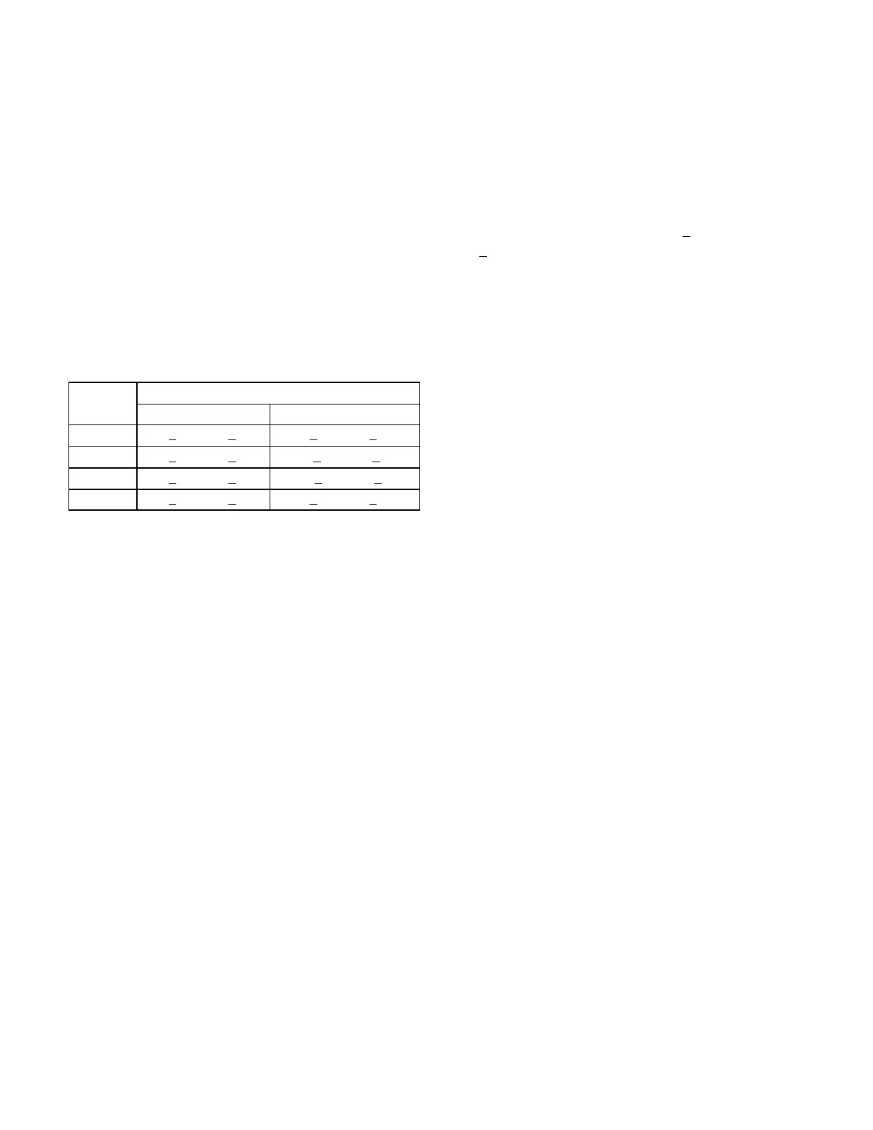
TABLE 15
APPROACH TEMPERATURE - Fin/Tube - TXV
Unit
Liquid Temp. Minus Ambient Temp.
1st Stage 2nd Stage
092S 7°F + 1 (3.9°C + 0.5) 9°F + 1 (5.0°C + 0.5)
102S 5°F + 1 (2.8°C + 0.5) 15°F + 1 (8.3°C + 0.5)
120S 3°F + 1 (1.6°C + 0.5) 2.0°F + 1 (1.1°C + 0.5)
150S 1°F + 1 (0.6°C + 0.5) 3°F + 1 (1.6°C + 0.5)
E-Compressor Controls
See unit wiring diagram to determine which controls are
used on each unit. Optional controls are identified on
wiring diagrams by arrows at junction points.
1- High Pressure Switches (S4, S7)
Compressor circuits are protected by a high pressure
switch which cuts out at 640 psig +
10 psig (4413 kPa
+
70 kPa).
2- Freezestats (S49, S50)
Switches de-energize compressors when evaporator
coil temperature falls below 29°F (-2°C) to prevent
evaporator freeze-up. Switches reset when
evaporator coil temperature reaches 58°F (15°C).
3- Crankcase Heater (HR1, HR2)
Compressors have belly band compressor oil heaters
which must be on 24 hours before running
compressors. Energize by setting thermostat so that
there is no cooling demand, to prevent compressor
from cycling, and apply power to unit.

 Loading...

