Page 29
Set Low Speed Minimum Position
1- Initiate a blower (G) only AND occupied demand from
the room thermostat or control system.
2- Set the ventilation speed switch on the VFD control
board to “LO”.
3- Rotate the low speed potentiometer on the VFD
control board to set the low speed minimum damper
position.
4- Measure the intake air CFM. If the CFM is lower than
the design specified CFM for ventilation air, use the
potentiometer to increase the damper percent open.
If the CFM is higher than specified, decrease the
damper percent open.
Note - Intake air CFM can also be determined using the
outdoor air temperature, return air temperature and
mixed air temperature. Refer to the economizer or
outdoor air damper installation instructions.
Troubleshoot LVC2 Board (A183)
Refer to wiring diagram sections B (unit), C (control) and
D (economizer) located on inside of unit panels.
1- Inspect the LVC2 for damaged components. Replace
the LVC2 if damaged components are found.
2- Check all wire connections to LVC2; secure if loose.
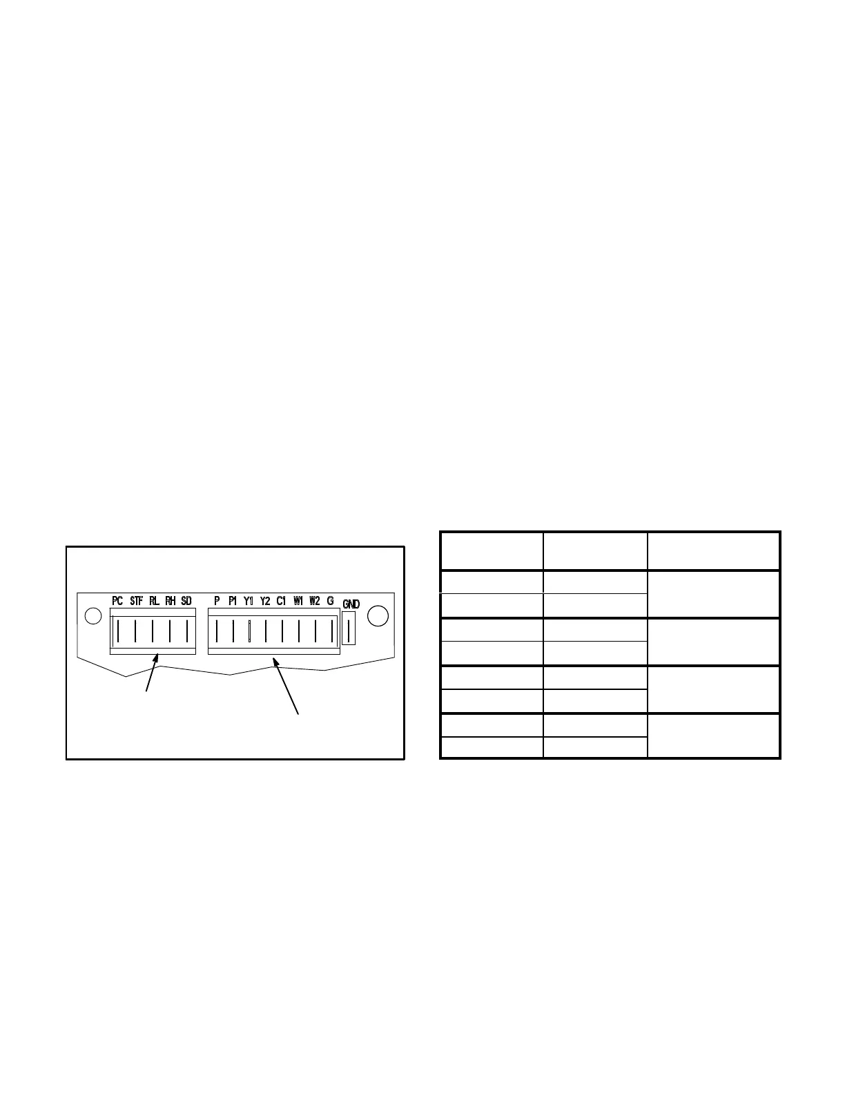
3- Check for 24VAC signal at the thermostat blower
input (G to GND terminal). See figure 23.
FIGURE 23
LVC2 BOARD TERMINAL DESIGNATIONS
24VAC
THERMOSTAT INPUTS;
H1 HEADER
24VDC
LVC2 OUTPUTS/
VFD INPUTS;
H2 HEADER
4- If there is no thermostat signal, troubleshoot back
toward the thermostat.
5- Check the power LED on the board. See figure 22.
6- If the power LED is not on, check voltage between
LVC2 terminals PC (H2-1) and SD (H2-5). Voltage
should read 24VDC.
7- If voltage does not read 24VDC, disconnect the H2
header from the LVC2 VFD terminal block (to make
sure the LVC2 is not shorting 24VDC supply from the
inverter). Measure the voltage between the end
terminals on the H2 header. If 24VDC is present,
replace the LVC2 board. If no voltage is read,
troubleshoot the VFD.
8- When LVC2 24VAC thermostat blower (G) input and
24VDC power are present, check the LVC2 low and
high speed outputs. The LVC2 uses inverse logic to
enable the blower; 1VDC will be read at the enabled
blower speed terminal. See table 17.
9- If all inputs are correct and the unit still does not
operate as intended, replace LVC2 board.
TABLE 17
LVC2 BOARD BLOWER OUTPUTS
Output
Terminals
Voltage Blower Operation
RL-SD 1VDC
Low Speed
RH-SD 24VDC
RL-SD 24VDC
High Speed
RH-SD 1VDC
RL-SD 1VDC
Illegal State
(replace board)
RH-SD 1VDC
RL-SD 24VDC
Blower Off
(replace board)
RH-SD 24VDC

 Loading...

