Page 7
Electrical Connections
POWER SUPPLY
A-Wiring
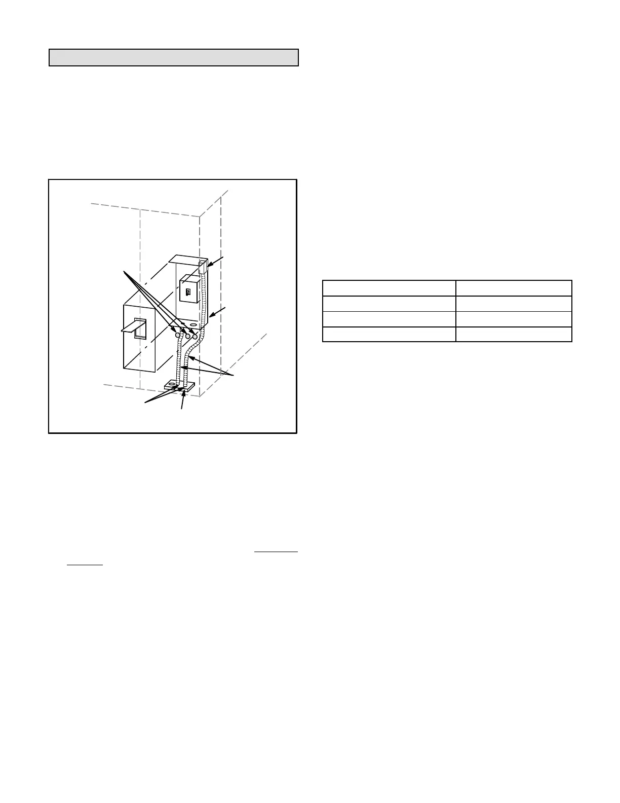
Route field wiring in conduit between bottom power entry
disconnect. See figure 8. This does not supersede local
codes or authorities having jurisdiction.
SEAL
WATERTIGHT
RUN FIELD
WIRING IN
FIELD PRO
VIDED CONDUIT
SIDE ENTRY
KNOCKOUTS
BOTTOM
POWER ENTRY
OPTIONAL
120V GFI
MAKE-
UP BOX
FIGURE 8
FIELD WIRE ROUTING
Do not apply power or close disconnect switch until
installation is complete. Refer to start-up directions.
Refer to unit nameplate for minimum circuit ampacity
and maximum fuse size.
1- 230,460,575 volt units are factory wired. For 208V
supply, disconnect the pink wire (230V) at all
control power transformer(s). Reconnect the pink
wire to terminal marked 208 on power
transformer(s). Tape the exposed end of the 230V
pink wire.
2- Route power through the bottom power entry area
and connect to L1, L2, and L3 on the bottom of F4
in the control box. Route power to TB2 on units
equipped with electric heat. Route power to S48
disconnect switch when the option is
factory-installed. See unit wiring diagram.
3- Connect separate 120v wiring to optional GFCI
outlet pigtails. Route field wiring in conduit between
bottom power entry and GFCI. See figure 8.
B-Unbalanced Three-Phase Voltage - VFD Units Only
Units equipped with an optional inverter (VFD) are
designed to operate on balanced, three-phase power.
Operating units on unbalanced three-phase power will
reduce the reliability of all electrical components in the
unit. Unbalanced power is a result of the power delivery
system supplied by the local utility company.
Factory-installed inverters are sized to drive blower
motors with an equivalent current rating using balanced
three-phase power. When unbalanced three-phase
power is supplied; the installer must replace the existing
factory-installed inverter with an inverter that has a higher
current rating to allow for the imbalance. Use table 1 to
determine the appropriate replacement inverter.
TABLE 1
INVERTER UP-SIZING
Factory-Installed Inverter HP Replacement Inverter HP
2 5
3 7-1/2
5 10
CONTROL WIRING
A-Thermostat Location
Room thermostat mounts vertically on a standard 2” X 4”
handy box or on any non-conductive flat surface.
Locate thermostat approximately 5 feet (1524 mm)
above the floor in an area with good air circulation at
average temperature. Avoid locating the room
thermostat where it might be affected by:
-drafts or dead spots behind doors and in corners
-hot or cold air from ducts
-radiant heat from sun or appliances
-concealed pipes and chimneys
IMPORTANT - Unless field thermostat wires are rated
for maximum unit voltage, they must be routed away
from line voltage wiring.
B-Control Wiring
1- Route thermostat cable or wires from subbase to
unit control box (refer to unit dimensions to locate
bottom and side power entry).
IMPORTANT - Unless field thermostat wires are rated
for maximum unit voltage, they must be routed away
from line voltage wiring. Use wire ties located near the
front of the control section to secure thermostat cable.
Use18 AWG wire for all applications using remotely
installed electro-mechanical and electronic
thermostats.
2- Install thermostat assembly in accordance with
instructions provided with thermostat.