8
Place the battery in the unit and ensure the positive side of the
battery is in accordance with the polarity markings.(See Fig.3-8)
Set the correct time before operating. Batteries in the wired controller
can maintain the correct time during a power failure. When the power
is restored and the displayed time is not correct, replace the battery.
Fig 3-8
Fig 3-7
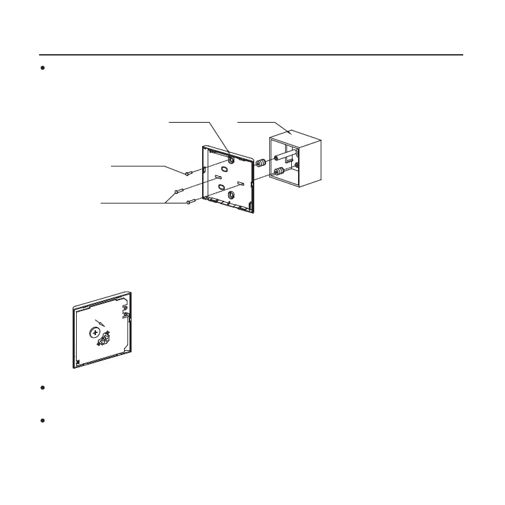
3. INSTALLATION METHOD
Switch box
Back plate
For switch box mounting, fasten the back plate on the switch box with
2 screws (M4x25) and fasten it on the wall with 1 screw (M4x20).
(Fig.3-7)
6. Battery installation
Screw (M4×20)
Screws (M4×25)
NOTE: Place on a at surface. Be careful not to distort the wire
controller’s back plate by over−tightening the mounting screws.
 Loading...