Do you have a question about the Lennox KJR-120G1/TFBG-E and is the answer not in the manual?
Confirms all supplied parts and prepares site assemblies before installation.
Precautions for wiring and grounding the wired controller during installation.
Details the physical dimensions of different wired remote controller models.
Illustrates wiring connections between controller and indoor unit mainboard.
Shows the physical wiring process for specific models KJR-120G2/TFBG-E(12V) & KJR-120H2/TFBG-E.
Details wiring for KJR-120G1/TFBG-E(5V) using an adapter board.
Instructions for carefully removing the upper part of the wired controller.
Guidance on securing the back plate to the wall for surface mounting.
Instructions for fastening the back plate to a switch box and the wall.
Steps for correctly installing the battery and setting the initial time.
Describes three methods for wiring the indoor unit to the controller.
Reassembling the controller upper part, avoiding wire clamping.
Opening the indoor unit's front panel to begin kit installation.
Steps to disconnect the existing wire from the main controller board.
Identifies controller, convert board, and display board for the kit.
Locates CN201 connection on display board for main board wiring.
Identifies CN101 connection from display board to convert board.
Instructions for removing the display board from the front panel.
Instructions to break off a specific rectangular section of the display board.
Replacing old display board with new and securing it with clips.
Instruction to remove screen cover from display board before reassembly.
Details connecting wires from display board to convert board.
Connects wire from wired remote controller to convert board.
Steps for installing cover, mounting boards, and connecting components.
Guide to setting the current day and time on the wired controller.
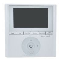
Instructions on how to start and stop the air conditioner operation.
How to select the desired operating mode (Auto, Cool, Dry, Heat, Fan).
Adjusting the desired room temperature within the specified range.
Adjusting the fan speed to Auto, Low, Medium, or High.
Choosing whether to use the indoor unit or controller for temperature sensing.
Activating and deactivating the child lock to prevent unintended changes.
Enabling or disabling the audible keypad tone.
Switching the temperature display between Celsius and Fahrenheit.
Using Turbo mode for faster heating/cooling and Auxiliary Heat.
Controlling the lift and drop of the panel on cassette-specific models.
Operating the up-down swing function for airflow direction.
Operating the left-right swing function for airflow direction.
Setting operating times for each day of the week.
Setting the timer to start air conditioner operation.
Setting the timer to stop air conditioner operation.
Setting timers for both starting and stopping air conditioner operation.
Step-by-step guide to setting the On or Off timer.
Step-by-step guide to setting both the On and Off timers.
Initiating the weekly timer setup by selecting 'Week'.
Selecting the specific day of the week for timer settings.
Setting the ON time, mode, temperature, and fan speed for a timer event.
Setting the specific time for a weekly timer event.
Selecting the operation mode for a weekly timer event.
Setting the room temperature for a weekly timer event.
Setting the fan speed for a weekly timer event.
Repeating steps to set multiple scheduled events within a day.
Adding timer settings for additional days in a week.
Starting and canceling the weekly timer operation.
Configuring a 'Day Off' setting for holidays within the weekly timer.
Using the DAY OFF function to mark specific days as non-operational.
Copying timer settings from one day to another.
Steps to copy timer settings from one day to another, confirming the operation.
Procedure to delete a specific time scale entry from a daily schedule.
| Model Number | KJR-120G1/TFBG-E |
|---|---|
| Category | Remote Control |
| Power Source | Battery |
| Display Type | LCD |
| Functionality | Controls temperature, fan speed, mode, and other settings |
| Compatibility | Lennox HVAC systems |
| Range | Up to 8 meters |