5
3. INSTALLATION METHOD
Fig 3-3
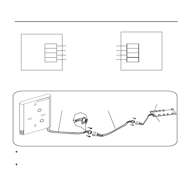
2.Wiring Connection Diagram
red
black
yellow
brown
red
black
yellow
brown
Insert of the
mainboard CN40
Wire controller
Indoor unit mainboard
4-Core Shield Cable, the length
is decided by installation
-----------------------------------
-----------------------------------
-----------------------------------
-----------------------------------
Connect the female joint of the wires group from the mainboard
with the male joint of the connective wires group. (See Fig.3-4(A))
Connect the other side of the connective wires group with the male
joint of the wires group leads from the wire controller.(See Fig.3-4(A))
Fig 3-4(A)
Mainboard
4-core shielding wire
3.Wiring figure
Model :KJR-120G2/TFBG-E(12V) &KJR-120H2/TFBG-E
The connection cable
CN40
 Loading...