Page 41
D-ELECTRIC HEAT COMPONENTS
Electric heat match-ups are found in the ELECTRICAL
DATA tables. See table of contents.
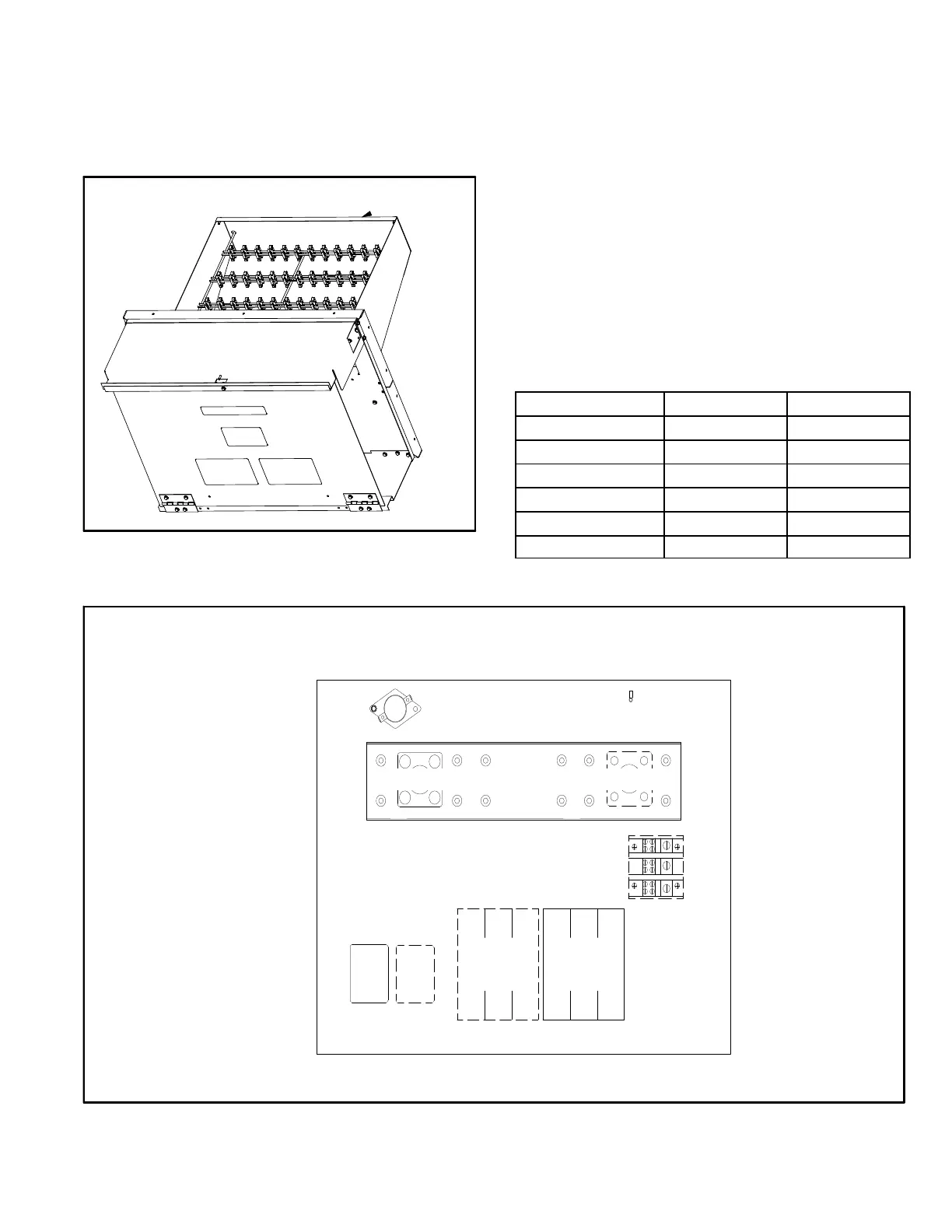
All electric heat sections consist of electric heating ele
ments exposed directly to the air stream. See figure 13.
See figure 14 for vestibule parts arrangement.
FIGURE 13
ELECTRIC HEAT ELEMENTS
1-Contactors K15, K16
All contactors are double break and either single,
double or three pole (see diagram) and equipped with
a 24VAC coil. The coils in the K15 and K16 contactors
are energized by the indoor thermostat. In all units
K15 energizes the heating elements, while in the 22.5
kW units, K15 and K16 energize the heating elements
simultaneously.
2-High Temperature Limits S15 (Primary)
S15 is a SPST N.C. auto‐reset thermostat located on the
back panel of the electric heat section above the heating
elements. S15 is the high temperature limit for the electric
heat section. When S15 opens, indicating a problem in the
system, contactor K15 is de‐energized (including K16 in
22.5 kW units). When K15 is de‐energized, all stages of
heat are de‐energized. See table 5 for S15 set points. Set
points are factory set and not adjustable.
TABLE 5
Unit kW (Voltage) S15 Opens ° F S15 Closes ° F
7.5 (Y, G, J, P) 160 120
15 (Y) 170 130
15 (G, J, P) 160 120
22.5 (Y, G, J) 160 120
22.5 (P) 150 110
30 (Y, G, J) 150 110
ELECTRIC HEAT COMPONENTS
FIGURE 14
S15
S20 S157
K15 K16
F42 F3
TB3
L1
L2
L3