Page 43
II-PLACEMENT AND INSTALLATION
Make sure the unit is installed in accordance with the
installation instructions and all applicable codes. See
accessories section for conditions requiring use of the
optional roof mounting frame (T1CURB-AN or
C1CURB-AN).
III-START UP - OPERATION
A-Preliminary and Seasonal Checks
1- Make sure the unit is installed in accordance with the
installation instructions and applicable codes.
2- Inspect all electrical wiring, both field and factory
installed for loose connections. Tighten as required.
Refer to unit diagram located on inside of unit compres
sor access panel.
3- Check to ensure that refrigerant lines are in good
condition and do not rub against the cabinet or other
refrigerant lines.
4- Check voltage at the disconnect switch. Voltage must
be within the range listed on the nameplate. If not, con
sult the power company and have the voltage cor
rected before starting the unit.
5- Recheck voltage and amp draw with unit running. If
voltage is not within range listed on unit nameplate,
stop unit and consult power company. Refer to unit
nameplate for maximum rated load amps.
6- Inspect and adjust blower belt (see section on Blower
Compartment - Blower Belt Adjustment).
IV-CHARGING
WARNING-Do not exceed nameplate charge under any
condition.
A-Refrigerant Charge and Check - Fin/Tube Coil
This unit is factory charged and should require no further
adjustment. If the system requires additional refrigerant, re
claim the charge, evacuate the system, and add required
nameplate charge.
NOTE - System charging is not recommended below 60°F
(15°C). In temperatures below 60°F (15°C) , the charge
must be weighed into the system.
If weighing facilities are not available, or to check the
charge, use the following procedure:
1- Attach gauge manifolds and operate unit in cooling
mode on HIGH SPEED with economizer disabled until
system stabilizes (approximately five minutes). Make
sure outdoor air dampers are closed.
2- Use a thermometer to accurately measure the outdoor
ambient temperature.
3- Apply the outdoor temperature to tables 7 through 15
to determine normal operating pressures. Pressures
are listed for sea level applications at 80°F dry bulb and
67°F wet bulb return air.
4- Compare the normal operating pressures to the pressures
obtained from the gauges. Minor variations in these pres
sures may be expected due to differences in installations.
Significant differences could mean that the system is not
properly charged or that a problem exists with some com
ponent in the system. Correct any system problems be
fore proceeding.
5- If discharge pressure is high, remove refrigerant from
the system. If discharge pressure is low, add refrigerant
to the system.
S Add or remove charge in increments.
S Allow the system to stabilize each time refrigerant
is added or removed.
6- Use one of the following charge verification methods
along with the normal operating pressures to confirm
readings.
B-Charge Verification - Fin/Tube Coil - AHRI TESTING
Approach Method -
Standard and High Efficiency Units
1- Using the same thermometer, compare liquid tempera
ture to outdoor ambient temperature.
Approach Temperature = Liquid temperature (at con
denser outlet) minus ambient temperature.
2- Approach temperature should match values in table 16.
An approach temperature greater than value shown indi
cates an undercharge. An approach temperature less
than value shown indicates an overcharge.
3- The approach method is not valid for grossly over or
undercharged systems. Use tables 7 through 15 as a
guide for typical operating pressures.
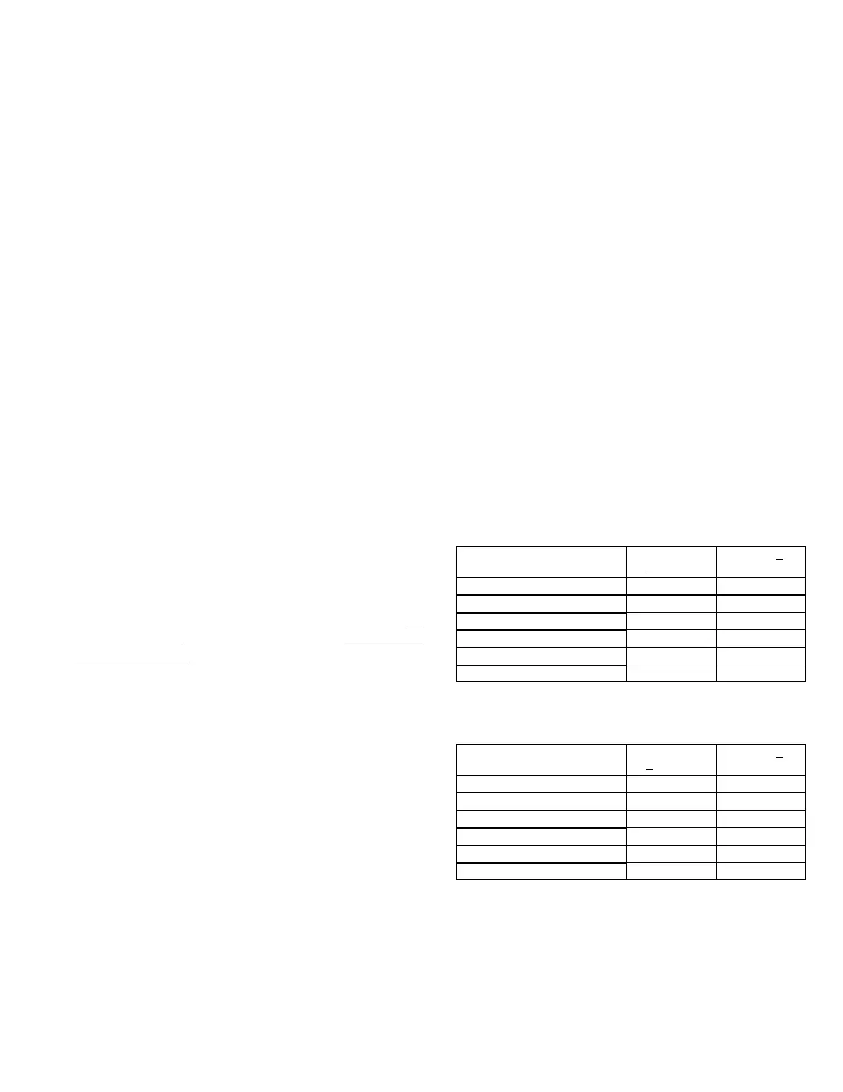
TABLE 7
LG/LC 036S/H NORMAL OPERATING PRESSURES
Outdoor Coil
Entering Air Temp
Discharge
+
10 psig
Suction + 5
psig
655 F 265 140
755 F 299 143
855 F 348 145
955 F 394 148
1055 F 445 150
1155 F 500 153
TABLE 8
LG/LC 036S/H REHEAT NORMAL
OPERATING PRESSURES
Outdoor Coil
Entering Air Temp
Discharge
+
10 psig
Suction + 5
psig
655 F 262 139
755 F 300 141
855 F 342 144
955 F 388 148
1055 F 437 150
1155 F 491 153
 Loading...


