Page 16
Temperature Sensors
The return air (RT16) and discharge air (RT6) duct probes
and the outdoor air (RT17) are all two wire thermistors. The
resistance vs. temperature table is shown below:
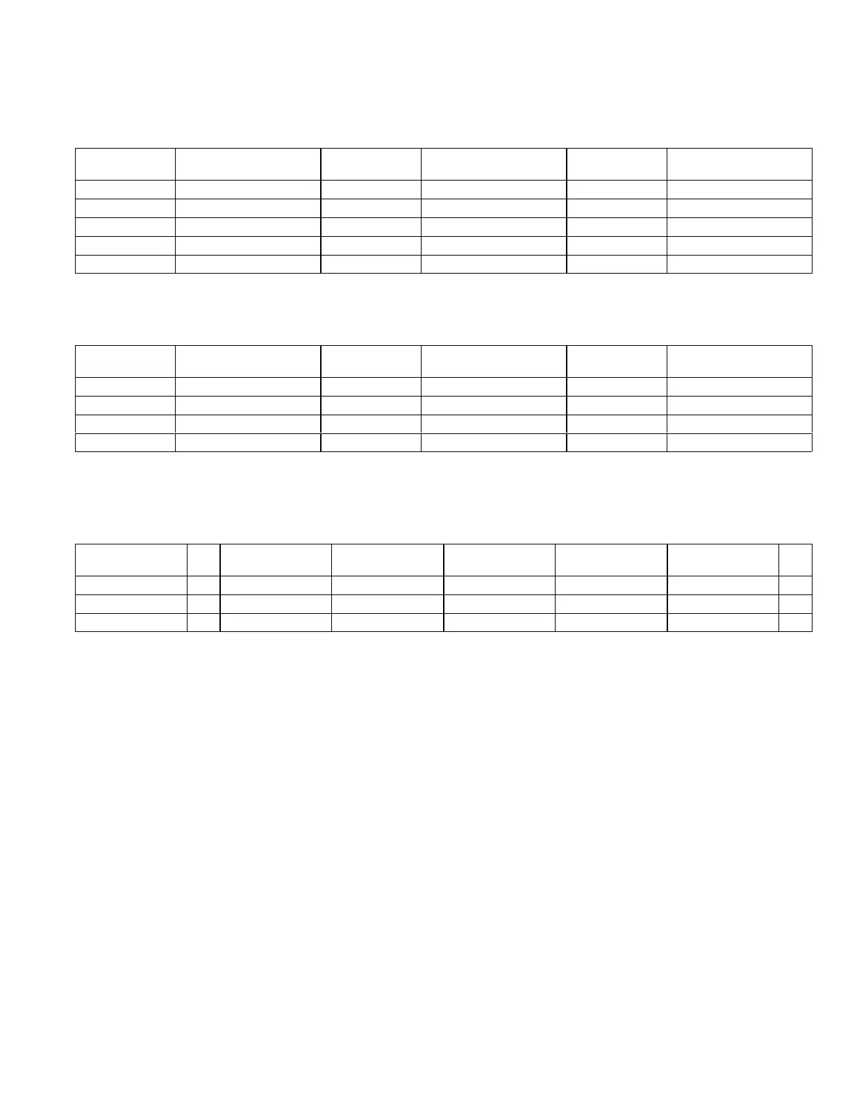
Table 1
Resistance vs. Temperature
Temp. °F (°C) Resistance +/-2%
Temperature °F
(°C)
Resistance +/-2% Temp. °F (°C) Resistance +/-2%
-40 (-40) 335,671 40 (4.4) 26,106 90 (32.2) 7,332
-20 (-28.9) 164,959 50 (10) 19,904 100 (37.8) 5,826
0 (-17.8) 85,323 60 (15.6) 15,313 120 (48.9) 3,756
20 (-6.7) 46,218 70 (21.1) 11,884 130 (54.4) 3,047
30 (-1.1) 34,566 80 (26.7) 9,298
Room Sensors
Room sensor (A2) is a two-wire thermistor with 1k series resistor.
Table 2
Two-Wire Thermistor
Temp. °F (°C) Resistance +/-2%
Temperature °F
(°C)
Resistance +/-2% Temp. °F (°C) Resistance +/-2%
40 (4.4) 27,102 60 (15.6) 16,313 80 (26.7) 10,299
45 (7.2) 23,764 65 (18.3) 14,474 85 (29.4) 9,249
50 (10) 20,898 70 (21.1) 12,882 90 (32.2) 8,529
55 (12.8) 18,433 75 (23.9) 11,498
Carbon Dioxide Sensor
The indoor carbon dioxide sensor (A63) is an analog sensor with a 0-10VDC output over a carbon dioxide range of 0-2000
ppm as shown in the following table. The sensor is powered with 24VAC.
Table 3
Carbon Dioxide Range
Carbon Dioxide
PPM
DC
V
Carbon Dioxide
PPM
DC Voltage
Carbon Dioxide
PPM
DC Voltage
Carbon Dioxide
PPM
DC
V
0 0 600 3 1200 6 1800 9
200 1 800 4 1400 7 2000 10
400 2 1000 5 1600 8
Relative Humidity Sensor - Optional
The indoor relative humidity sensor (A91) is an analog
sensor with a 0-10VDC output over a relative humidity
range of 0-100% relative humidity. The sensor is powered
with 24VAC.
Enthalpy Sensor - Optional
The optional enthalpy sensors (A7 and A63) used with the
economizer have an output of 4-20mA. The sensor is
powered with 18VAC provided by M3 unit control.
Economizer Differential Pressure Sensor - Optional
Rooftop units installed with Smart Airflow™ will have a
Pressure Transducer (PT5) present in the economizer.
PT5 requires 5VDC power supply (P266-5 and {P266-6)
and gives 0.25 VDC to 4 VDC output (P266-4)
corresponding to 0” water column and 2” water column
respectively. For all practical purposes the output should
be less than 1.2” water column if not an error code is stored
and service alarm output is turned on.
15-Second-Stage Power Exhaust Relay
K231 (Staged-Blower units equipped
with power exhaust)
The second power exhaust fan is controlled by K231. A133
will enable K231 only when the blower reaches 70% of full
speed (adjustable ECTO). This prevents a negative
building pressure when the blower is operating in low
speed. Refer to the Unit Controller manual and ECTO
labels on the unit.
16-Fuse F61 (Higher SCCR units only)
Fuse F61 is used on units with higher SCCR rating. F61
provides overcurrent protection to compressor and other
cooling components. F61 and S48 are located inside a
sheet metal enclosure in the unit left front corner mullion.
17-Blower Motor Overload Relay S42
The relay (S42) is connected in line with the blower motor to
monitor the current flow to the motor. When the relay
senses an overload condition, a set of normally closed
contacts open to de-energize pin #1 in plug P299 of the A55
Unit Controller. A55 de-energizes all outputs. Units will be
equipped with a relay manufactured by Telemecanique
figure 5 or Siemens figure 6.
 Loading...
