Page 47
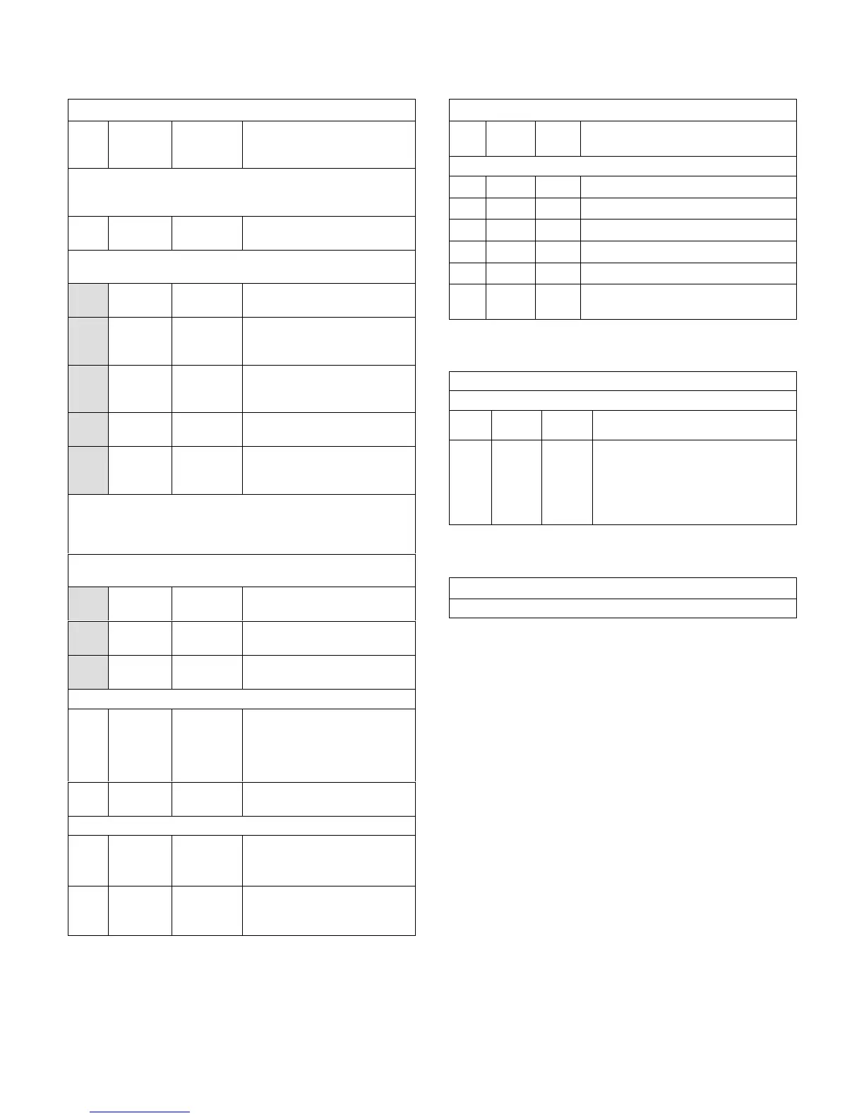
TABLE 37
580683
LGH/LCH 094U4E (2-Compressor) Staged Direct Drive
Para
met
er
Factory
Setting
Field
Setting
Description
Note: Any changes to Smoke CFM setting must be adjusted be
fore the other CFM settings. Use SETTINGS > RTU OPTIONS >
EDIT PARAMETERS
12
3000
CFM
CFM
Blower CFM during smoke
detection.
SETUP > TEST & BALANCE (can also use SETTINGS > RTU
OPTIONS > BLOWER > SPEEDS)
3000
CFM
CFM
Blower CFM during heating.
3000
CFM
CFM
Blower CFM during high speed
cooling (2 compressor)
operation.
1950
CFM
CFM
Blower CFM during low speed
cooling (1 compressor)
operation.
3000
CFM
CFM
Blower CFM during ventilation.
1195
RPM
RPM*
Adjust RPM based on unit static
and blower tables to reach tar
get CFM.
*Once all four blower settings are entered, the target (highest of the
heating and cooling settings) CFM will be displayed. Once the RPM
is saved for the target CFM, all other blower RPM values are set by
the Unit Controller according to the field CFM setting..
SETUP > TEST & BALANCE (can also use SETTINGS > RTU
OPTIONS > DAMPER)
0% %
Damper min. position during
LOW blower operation.
0% %
Damper min. position during
HIGH blower operation.
0% %
Power exhaust position during
HIGH blower operation.
SETTINGS > RTU OPTIONS > EDIT PARAMETERS
29 101% %Open
Damper minimum position during
G blower operation. (Setting para
meter 29 to “101” disables para
meter 29 and passes control to
parameter 9 or 132)
216 5% %
Deadband % for stage 1 power
exhaust operation.
SETTINGS > RTU OPTIONS > EDIT PARAMETER
85 40°F °F
Compressor 1 low temp lockout.
Settings lower than 40°F could
void warranty.
86 40°F °F
Compressor 2 low temp lockout.
Settings lower than 40°F could
void warranty.
TABLE 38
580731
Units With Automated Logic DDC (Target) Settings
Para
meter
Factory
Setting
Field
Setting
Description
Use SETTINGS > RTU OPTIONS > EDIT PARAMETERS
91 120 Compressor minimum run time.
111 3 Thermostat with three cooling stages.
118 400 Damper “start open” CO
2
setpoint for DCV.
119 2000 Damper “full open” CO
2
setpoint for DCV.
139 74 Backup occupied cooling setpoint.
153 60
Time delay between heating and cooling
mode.
TABLE 39
580734
Units With Hot Gas Reheat
Use SETTINGS > RTU OPTIONS > EDIT PARAMETERS
Para
meter
Factory
Setting
Field
Setting
Description
105 6
Hot Gas Reheat Option 6: Reheat is
only possible if blower is energized dur
ing occupied periods. Controlled by RH
sensor (A91) connected to input
A55_P298_5 and set point set at para
meter 106 (default 60%).
TABLE 40
580743
Units With LonTalk Settings
Use menu SETUP > NETWORK INTEGRATION. Set “LONTALK”.

 Loading...


